ssp
-
Posts
659 -
Joined
-
Last visited
-
Days Won
4
Content Type
Profiles
Forums
Blogs
Gallery
Everything posted by ssp
-
After playing around with the code it looks like what i am after cant be done, it's ok not an issue as i will be labeling everything anyway. today i finished the build on the MIDI_IO module, got it connected and after setting up a button as a note and defining the ports it worked fine sending out a midi to my XV1A synth build Now everything is running its time to work on the eurorack style control faceplates
-
I wonder if you would use it in this way as an example? if ^section == 1 if ^bank == 1 log "bank 1 selected" set label="LFO FREQ:%3d" elseif ^bank == 2 log "bank 2 selected" set label="LFO RES:%3d"
-
Thanks for the pointer Thomas, I did look through the info and the Label section, nothing there to show mapping labels. I will have another read through the Ngr docs this week and try things this weekend when I am off work. Thanks again
-
can you call "labels" from a map? rather than using this label="LFO FREQ:%3d" can you have it call the label from a map and when the button is pressed it displays this label rather than waiting for you to say turn the encoder then it displays the label?
-
Really pleased for you @Smithy they have come out really good. Shame about the scuffs, make sure you email them highlighting the damage and your payment for correct shipping, they may offer replacements. Looking forward to seeing the build!!!
-
Back in the land of buildz. Using the above code I have modified it so that using two buttons i can move up and down the 3 digit displays and using a single encoder change the values. i am using this just or dec and inc through the 3 digit displays When i press the button it doesnt display the correct text on the main lcd display until i move the encoder. EVENT_ENC id=1 hw_id= 1 bank= 1 fwd_id=LED_MATRIX:1 type=CC chn= 1 cc= 16 range=0:127 fwd_id=SENDER:1 EVENT_ENC id=2 hw_id= 1 bank= 2 fwd_id=LED_MATRIX:4 type=CC chn= 1 cc= 17 range=0:127 fwd_id=SENDER:2 EVENT_ENC id=3 hw_id= 1 bank= 3 fwd_id=LED_MATRIX:4 type=CC chn= 1 cc= 18 range=0:127 fwd_id=SENDER:3 here is the dout code, you can see where i am forwarding to the lcd underlined text. it forwards the map for -99 to 99 and the label to the lcd EVENT_BUTTON id= 1 type= Meta meta= DecBank meta= RunSection:1 button_mode= OnOnly #Bank decrease EVENT_BUTTON id= 2 type= Meta meta= IncBank meta= RunSection:1 button_mode= OnOnly #Bank increase EVENT_SENDER id=1 fwd_id=LED_MATRIX:1 range=map1 EVENT_SENDER id=2 fwd_id=LED_MATRIX:4 range=map1 EVENT_SENDER id=3 fwd_id=LED_MATRIX:17 range=map1 # First Value (3 digits) received via CC#16 EVENT_LED_MATRIX id=1 fwd_id=LED_MATRIX:2 led_matrix_pattern=Digit1 range=-99:99 fwd_to_lcd=1 lcd_pos=1:1:2 label="LFO FREQ:%3d" EVENT_LED_MATRIX id=2 fwd_id=LED_MATRIX:3 led_matrix_pattern=Digit2 range=-99:99 EVENT_LED_MATRIX id=3 led_matrix_pattern=Digit3 range=-99:99 # Second Value (3 digits) received via CC#17 EVENT_LED_MATRIX id=4 fwd_id=LED_MATRIX:5 led_matrix_pattern=Digit1 range=-99:99 fwd_to_lcd=1 lcd_pos=1:1:2 label="LFO RES:%3d%B" EVENT_LED_MATRIX id=5 fwd_id=LED_MATRIX:6 led_matrix_pattern=Digit2 range=-99:99 EVENT_LED_MATRIX id=6 led_matrix_pattern=Digit3 range=-99:99 # Third Value (3 digits) received via CC#18 EVENT_LED_MATRIX id=17 fwd_id=LED_MATRIX:18 led_matrix_pattern=Digit1 range=-99:99 fwd_to_lcd=1 lcd_pos=1:1:2 label="LFO MODE:%3d%B" EVENT_LED_MATRIX id=18 fwd_id=LED_MATRIX:19 led_matrix_pattern=Digit2 range=-99:99 EVENT_LED_MATRIX id=19 is there a way i can when i press the + button that it changes the text to the text that is mapped eg: first 3 digits called "lfo freq" second called " lfo res" third called "lfo mode" on boot up its set to show lfo freq, if i then press the + button it shows "lfo res" on the display rather than changing it when i move the encoder, if i press + again lfo mode, then the same going back down etc. also a third button that just when pressed goes to the first or home which is the first 3 digits "lfo freq". do i alter the ngc or ngr? the ngr here was used to light up an led for each bank i dont need that to happen now. ####### Section 0 ####### if ^section == 0 log "running section0" #initialize all banks to 1 log "call bank 1 for all parameters" set ^bank 1 exit endif ######################### ########## Section 1 ########### #tests for the current bank and lights the corresponding LED if ^section == 1 if ^bank == 1 log "bank 1 selected" set LED:1 1 elseif ^bank == 2 log "bank 2 selected" set LED:2 2 elseif ^bank == 3 log "bank 3 selected" set LED:3 3 elseif ^bank == 4 log "bank 4 selected" set LED:4 4 endif exit endif ################################ will try more tomorrow but a pointer is always appreciated. thanks.
-
Nice to be back in the forum after work life got in the way and things had to change! Bought my cnc machine from work along with the laster system, just finished re-wiring it and fitting new cable chains, new power chassis for the main drive system. I used to use it for making pcbs and enclosures and faceplates so good to have this for use now. Dug my projects out and looking forward to finishing them finally over the winter months, no questions from me, just time to get on with things!
-
Thats is some beautiful work there Phatline ;)
-
sorted ;)
-
I just got one of these to try here, all i am getting is just random pixels. https://www.diymore.cc/collections/led-display-module/products/2-42-inch-12864-oled-display-module-iic-i2c-spi-serial-for-arduino-c51-stm32-green-white-blue-yellow

-
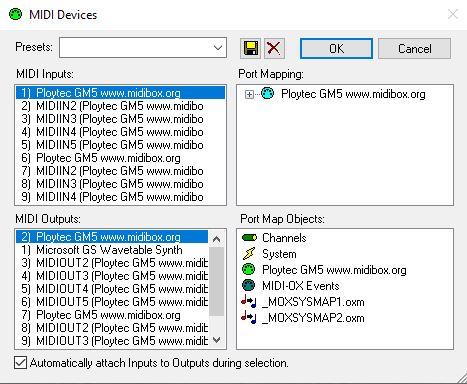
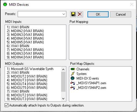
question!! so on my ng core i have set the core to have its own name and gave it a device id=127 (random pick) when i attach it to the pc it is picked up as normal however, when i then attach my gm5x5x5 to the computer all the ports are the same name if i plug in the gm5x5x5 first then the midibox ng it make all the ports the same as the ng core how do i resolve this any ideas? I have msg'd nils so waiting for some info ( hopefully) Update: solved found the info in the gm5 page at the bottom, good ol' Nils ;) Q: I want to use two GM5 modules for getting 10 MIDI IO ports, how can I give them individual names? A: Break the bridge at J8 of the PCB with a small screwdriver, so that IC2:IO4 is not connected to ground anymore. This selects the ploytec.com VID, so that your operating system can differ between two devices (midibox.org and ploytec.com) and installs an individual .inf file.
-
edit update: Managed to get the NG working with my XVA1 today, had a few issues with the crappy chinesium midi cable interface thingy, its in the bin now. used teh GM5x5x5 and all worked first time. working on using sys-ex with it, found an old post in the forum to help me with the sys-ex streams really love the .NG
-
thats ok Thomas ;) For now i will just bank things now i know how to, i need to learn a bit more about code writing etc before i jump into editing it. I am going to go through some of the tutorials in github and try a few other things out. there may be questions about code along the way, but only once i have written or edited things to try. Thanks again
-
Currently here : https://github.com/midibox/mios32/tree/master/apps/tutorials/005_polling_j5_pins before i go ZZZzz is this the right section to read through ( going to print it out if it is and mark things as I go ) to try and learn how to use the other pins, or do I need to look at other sections of code as well? The info i pasted above from Ucapps page doesn't really go into anything and it wasn't followed up. in github there is this for the Ain module: https://github.com/midibox/mios32/tree/master/apps/tutorials/012_ain_muxed however for the ainsermuxed: https://github.com/midibox/mios32/tree/master/apps/tutorials/012b_ainser_muxed there is nothing in there. I would really like to learn how to edit the pins on j5 to add ainser64's and compile etc. Thanks.
-
Hi Thomas the only thing i can find that maybe along those lines is this thread from fantomxr but this is for ainser8 I know nothing about this code or how to edit or compile I am afraid, so any pointers or help etc would be welcome for me. little bits make sense but I am no coder I am afraid.
-
Question: On the Ainser64 info page it states that more than 2 ainser64 can be used: (i want to have 3 ainser64 connected using their own power feed in rather than from the core) Multiple MBHP_AINSER64 (or MBHP_AINSER8) modules are connected to J19 in parallel, and accessed by strobing dedicated chip select lines. J19 provides two chip selects (called "RC1" and "RC2"), if more modules should be scanned, common IO pins could be used for the same purpose (e.g. available at J5). To programmers: alternatively, AINSER64 modules could be chained, or a 3-to-8 MUX could be used for accessing 8 modules via 3 IO pins of the microcontroller. Does the underlined statement refer to j5a and j5b on the core board? Would i need to edit the mios for this or just the NGC file? I cannot find an example or any info for this. Thanks
-
Many thanks Thomas, with the code and the other edits it is working , i will edit the main code for the 16 3 digit lcds tomorrow after work and see if it does the job.
-
Thanks Thomas, The fwd_led i tried earlier but it wasn't playing ball for me. The build will have an dec bank and inc bank pair of buttons, with the leds above them 16 mini leds in all, this is just to give visual info on which one is selected. to sweep the cc# from 0:127 I will just use a single encoder. I have all of this working all bar the dec-inc leds so i will give this a try again, if no joy i will check the rats nest incase something is astray. Thanks as always.
-
Can you have more than one meta event mapped to a button press at the same time?
-
there isn't any real info on how I can do this, I have the bank code written and working yet don't seem to be able to assign a single led to a bank to show its active and then turn off when another bank is selected and that bank's led comes on. I have tried multiple versions of adapted code and do not seem to be getting anywhere. Searching the forum is hard work as it keeps erroring and not completing the search. I am going to try something in the .NGR script but even so I don't think that is the answer.
-
Looking over the .NGR info and I am wondering if in this instance would I use the .NGR script to have a single led per bank to show that bank is active? (reading mode activated in the meantime!!)
-
Question using the code above i edited to add banked leds. from this: # Bank 1 EVENT_AINSER id=1 hw_id =1 bank=1 fwd_to_lcd=1 type=CC chn=1 cc=16 range=0:127 offset=0 lcd_pos=2:1:1 label="FDR1 #%3i %3d@(2:1:2)%B" #Bank 2 EVENT_AINSER id=1 hw_id =1 bank=2 fwd_to_lcd=1 type=CC chn=1 cc=17 range=0:127 offset=0 lcd_pos=2:1:1 label="FDR2 #%3i %3d@(2:1:2)%B" To this: # Bank 1 EVENT_AINSER id=1 hw_id =1 bank=1 fwd_to_lcd=1 fwd_id=LED:1 fwd_to type=CC chn=1 cc=16 range=0:127 offset=0 lcd_pos=2:1:1 label="FDR1 #%3i %3d@(2:1:2)%B" #Bank 2 EVENT_AINSER id=1 hw_id =1 bank=2 fwd_to_lcd=1 fwd_id=LED:2 type=CC chn=1 cc=17 range=0:127 offset=0 lcd_pos=2:1:1 label="FDR2 #%3i %3d@(2:1:2)%B" However this just lit the led when the fader was moved and remained on when the bank was changed and then the other led came on and stayed on, not what i wanted. What i want is that when you press the bank buttons if you are on bank 1 then the led for bank one i9s lit, when you press the increment button to goto bank 2 led 1 goes out and led 2 for bank 2 come on press increment again and bank 3 led comes on and 2 goes out. how would i go about this? would i define an EVENT_LED id=1 and add functions to that or would i use a map? Thanks
-
Got it all running, used 3 buttons and two displays and a single fader, the code works really nicely and I got to grips with it finally, this is good as I will need multiple functions to map rather than have too fit individual parts everywhere! Code: RESET_HW LCD "%C@(1:1:1)Bank Test" # Controlled from buttons # select Bank1 directly EVENT_BUTTON id=1 type=Meta meta=SetBank button_mode=OnOnly range=1:1 # For testing purposes: decrement bank EVENT_BUTTON id=2 type=Meta meta=DecBank button_mode=OnOnly # For testing purposes: increment bank EVENT_BUTTON id=3 type=Meta meta=IncBank button_mode=OnOnly # For testing purposes: cycle bank EVENT_BUTTON id=4 type=Meta meta=CycleBank button_mode=OnOnly # Bank 1 EVENT_AINSER id=1 hw_id =1 bank=1 fwd_to_lcd=1 type=CC chn=1 cc=16 range=0:127 offset=0 lcd_pos=2:1:1 label="FDR1 #%3i %3d@(2:1:2)%B" #Bank 2 EVENT_AINSER id=1 hw_id =1 bank=2 fwd_to_lcd=1 type=CC chn=1 cc=17 range=0:127 offset=0 lcd_pos=2:1:1 label="FDR2 #%3i %3d@(2:1:2)%B" # AIN hardware AIN enable_mask=00000000 # AINSER hardware AINSER n=1 enabled=1 muxed=1 cs=0 num_pins=1 resolution=7bit AINSER n=2 enabled=0 muxed=1 cs=1 num_pins=0 resolution=7bit # EVENTs #EVENT_AINSER id= 1 type=CC chn= 1 cc= 16 range= 0:127 offset= 0 ports=1000100000001000 lcd_pos=2:1:1 label="^std_ain"
-
as soon as i have things set up and working i will share the pics and code as usual. just had to go out an buy a blooming piano for the kids.. electric!!
-
I have attached an ainser64 to the core and the jitter has gone, im just going to get my head around this now and re code things and test the banking again.