

Antichambre
-
Posts
1,291 -
Joined
-
Last visited
-
Days Won
101
Content Type
Profiles
Forums
Blogs
Gallery
Posts posted by Antichambre
-
-
On 6/10/2022 at 10:36 PM, tense said:
Ah, no complains from here!
Thanks for caring.
Seems like there exist a bunch of standard midi implementations.
Just ordered the Conduit - hope that works.
Best,
Tim
Something you can do is using the shield as ground, some recent machines doesn't provide GND on Midi out pin 2, there's a chance shield is connected, this cable adaptation needs the GND to work properly.
There's some explanation about it above in the thread. -
15 hours ago, tense said:
Any ideas on that? ...or is it just chance?
On my side it works with a MOTU fastlane or both MTPAV(old and USB model)
I think there's no rule, here I tried to find a workaround to avoid commercial boxes, I never said it will work without exception ;)
Still better to buy or build one of this active boxes, with optocoupler inside.
BR
Bruno -
Hi,
Mike is right, not like it is!
Crystal frequency change will oblige to change the configuration of the STM deeply to get its perpherals work at the right speed, the sd card uses quad spi instead of single one it's a new module to write, remap all pins etc etc...
Recompile a new bootloader because finally you will need you own version of MIOS32 to make it run. It's possible if you've got time and knowledge(or still more time to learn it).
BR
Bruno -
On 4/5/2022 at 12:12 AM, Spraytex said:
Idem, il va transformer mon AX80 , slurps.
Plus sérieusement, bravo pour le travail effectué, félicitations!
Si j'ai bien compris, il n'est pas polyphonique?
Merci d'avance pour la réponse.
Comme l'indique Raphaël(rmouneyres) c'est 8 voix en // qui basiquement font tourner 8 arpèges mono, le note off de la dernière note est toujours envoyé avant une nouvelle note, le GATE ne permet pas de chevauchement de note,
Il y a aussi une fonction avancée qui permet depuis un clavier midi de jouer des accords du même arpège, chaque note va déclencher un arpège qui sera transposé en fonction de la note joué.
On 4/4/2022 at 10:21 AM, electromaitre said:Salut bruno, on fait comment pour t'en acheter un ? ;o)
On patiente un peu encore ;)
-
-
Hi all,
I place this project here baecause it's more than a simple midification of a vintage synth.
Here is the only existing post which talk about this subject here
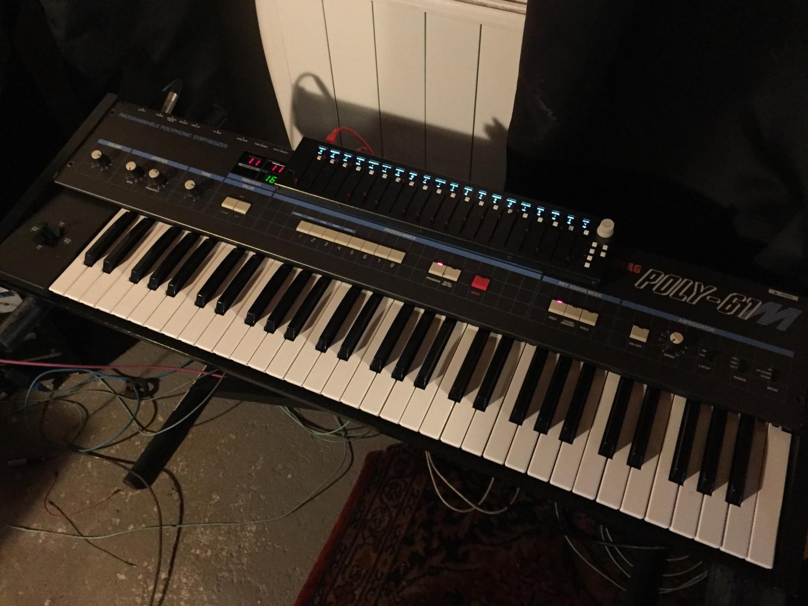
It already exists a few retro kit for the Korg Poly-61, but i wanted to fully upgrade my old Poly-61.
It's a synth I owned for free, it was found at the back of a concert hall, in the trash. I fixed and renovate it.
Symptoms were the common ones, battery leakage on the porgrammer board, wood parts and some keys were destroyed.
Once it was fixed I got a lot of fun with it, it sounds typically 80s with a fat analog vibe and i love that.
but using MIDI for pretty everything I was very frustrated by the lack of midi control and it's limited control panel.
So I started to study something better.
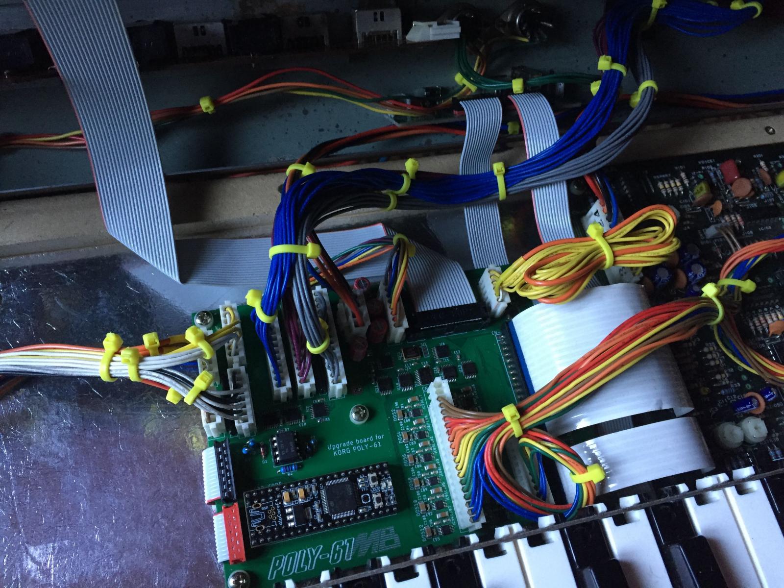
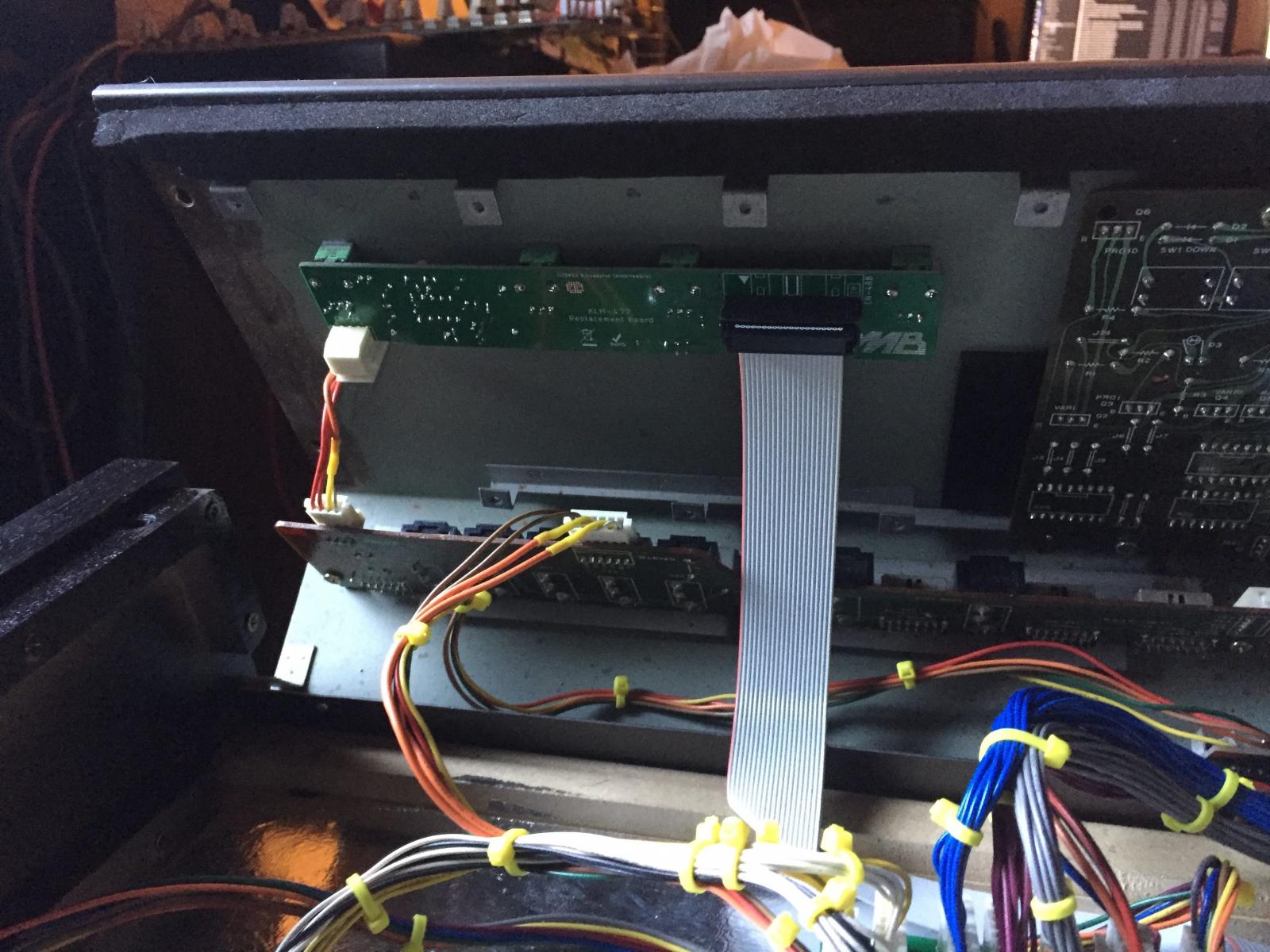
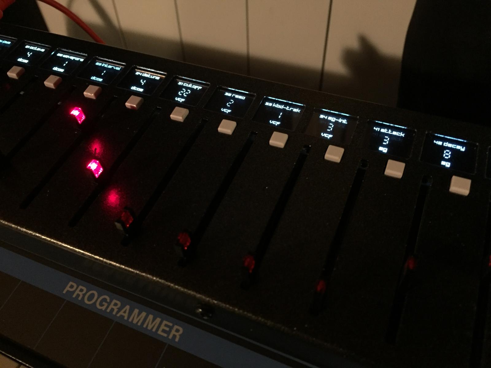
I replaced all the digital part of the synth by a MIDIbox based one, I kept all the signal path like it is.
I also reuse the existing control panel
I recreate the exact behavior of the original one in MIOS32, named LEGACY mode, the original factory presets were implemented too.
The useless TAPE ENABLE switch at the back is now a switch between the LEGACY mode and the EXTENDED mode, it enhances the parameters ranges and adds some new parameters.
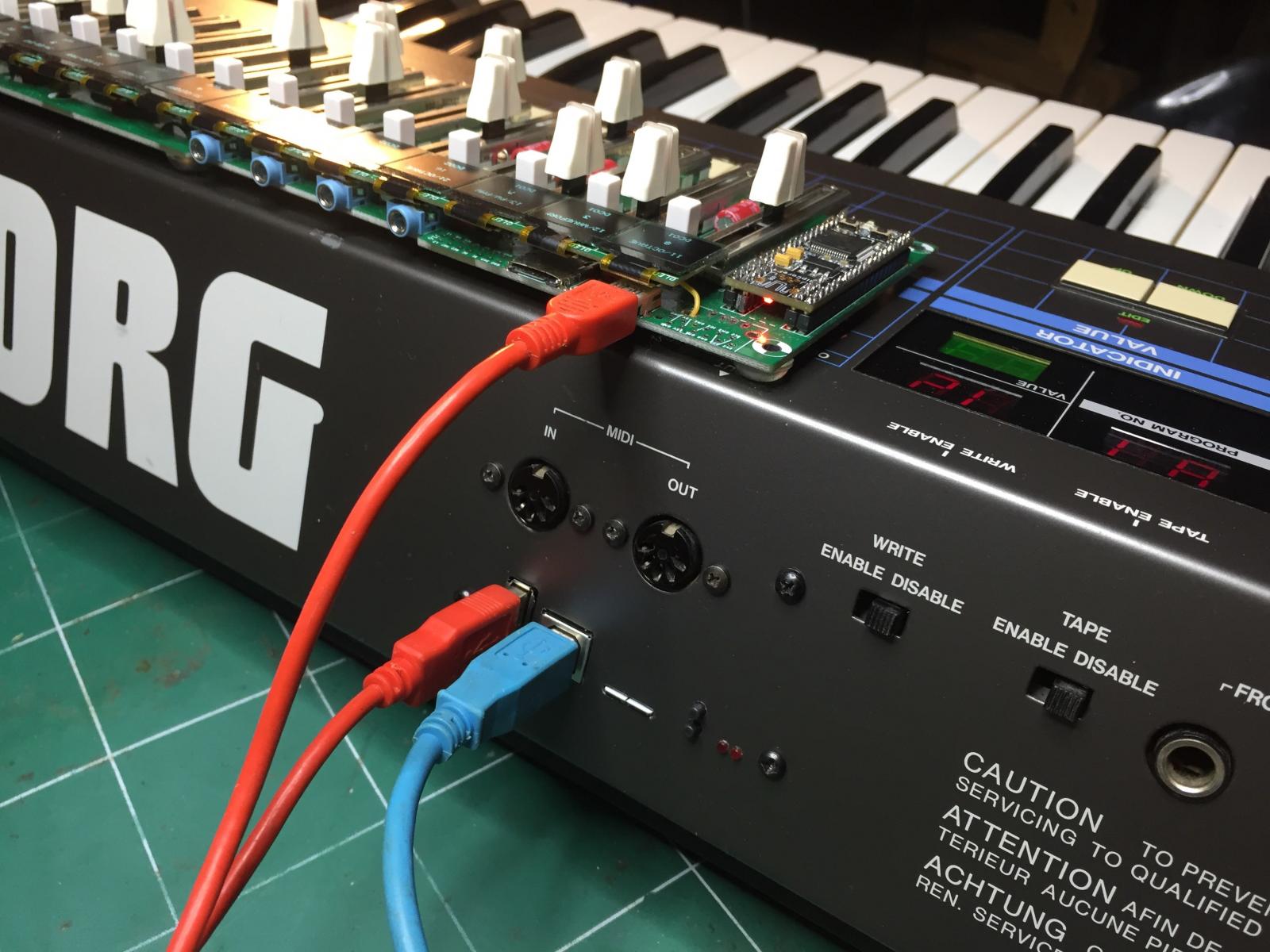
Finally I designed a dedicated Control surface which can be directly connected and powered to/by the Poly using USB.
The Poly has an USB device port to connect to a daw and an Host port to connect a MIDI controller.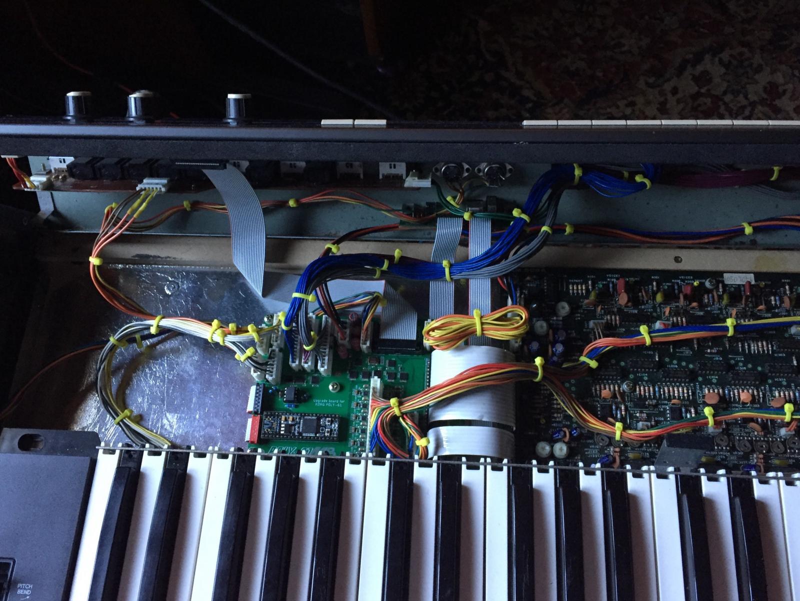
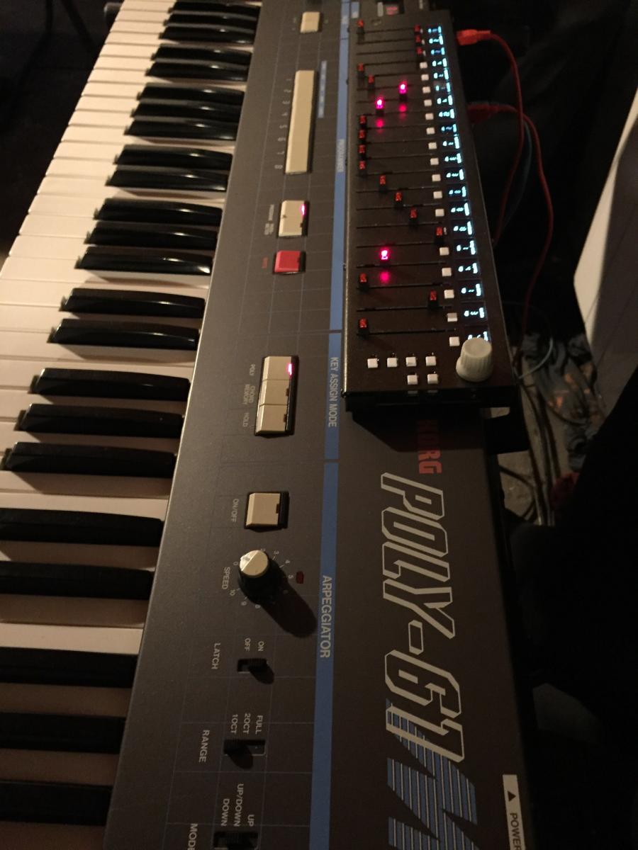
Voilà!
Best Regards
Bruno -
Hi Tony,
Not exactly the right place, here we talk about DIY MIDI Devices
There's no service manual/schematics available for this product, but.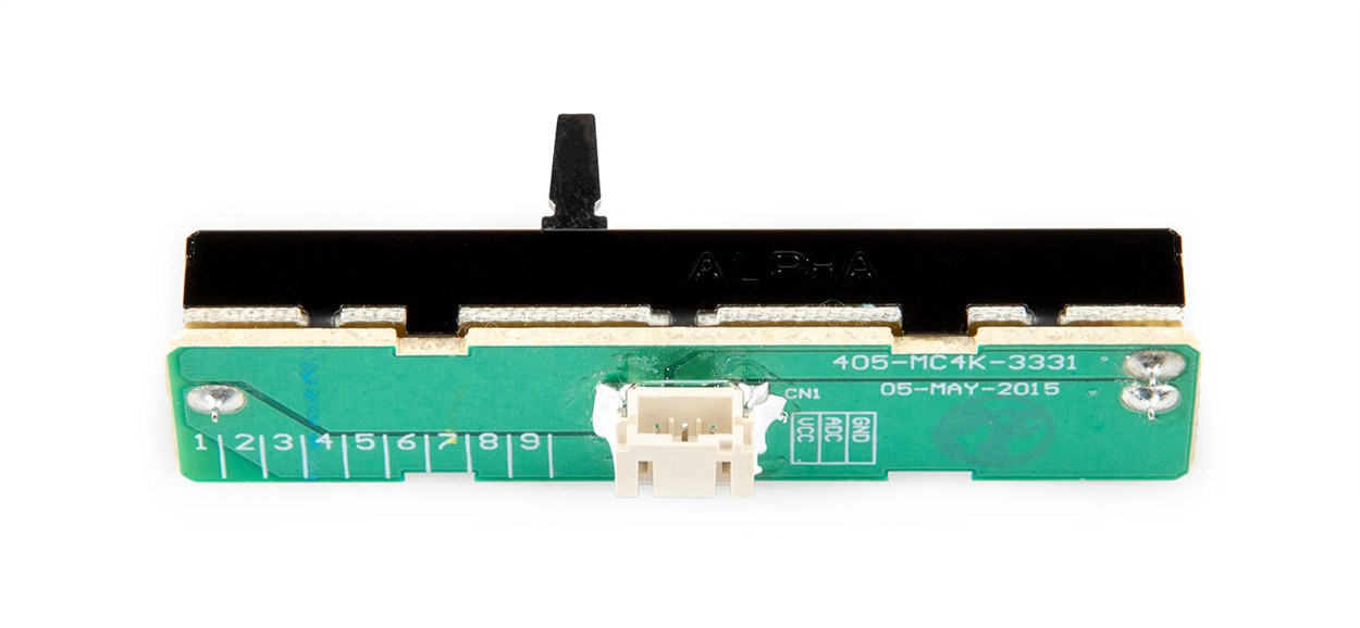 Denon DJ Replacement Crossfader for MCX8000/MC4000
As you can see, pinout of the connector CN1 is GND, ADC, VCC.
Means that pot drives an ADC(Analog to Digital Converter) with a ADC value range of GND to VCC
then ADC pin value range is ADC=GND (only channel A) to ADC=VCC (only channel B),
where center value is ADC=VDD/2 (both channels A and B mixed equally).
Both channels muted at the same time is not possible, using this ADC input.
Still possible to replace the fader, it's cheap ;)
Best regards -
Hi,
It seems not new.YMF825 (SD-1)
- Year of release: 2011
- FM: 16 channels (4-op, 29 waveforms)
- Used in: Home appliances (Chinese market)
This appears to be a version of MA-3. It has no PCM or Analog Lite capabilities. Using 2-op instruments does not give extra channels, thus it's probably best to use 4-op instruments.
https://gist.github.com/bryc/e85315f758ff3eced19d2d4fdeef01c5 -
On 4/28/2021 at 11:59 PM, Hawkeye said:
it's really true, it's his first one. he basically designed the PCBs and supported it for all those years without actually fully building one... hats off!)
Les cordonniers sont toujours les plus mal chaussés. -
A quick video demo, made by a friend. I just gave it to him like that, without much explanation.
The user manual is still not ready (blame me) but he managed to catch the thing even though he only used a few of the features.
-
 1
1
-
 1
1
-
-
On 4/9/2021 at 12:09 AM, FlavioB said:
Hey Bruno - would you mind give us all an update on the status of the HAARP project and the hardware enclosure? I haven't heard from you since February 2021...
Thanks!
I sent you a message.
-
So I don't know.
Try to change the MIDI channel according to its MIDI manual. -
Here is a normal MIDI interface schematic.
As you can see ground is only on pin 2 of the MIDI outputs.
I think your problem is that the chase bliss has no optocoupler input and doesn't get the signal between the regular pin 4 and 5(between signal and 5V) but between 4 and 2(signal and ground).
if no ground is provided on pin 2 of your controller then the pin4(signal) has no reference.
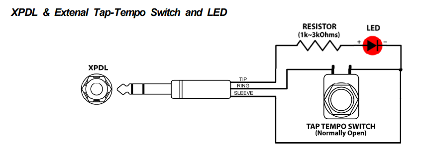
Before open the controller check the continuity between midi out pin 2 and another ground, e.g. sleeve of the XPDL jack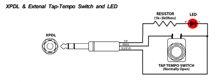
If there's nothing then open the enclosure and add it...
-
What is ISO cable? Regular MIDI one?
2 hours ago, Moulin said:could it make sense to rewire the Midi plug instead of messing with the controller?
Which plug?
-
Did you try to receive something from another machine(computer) to the chase bliss with this cable?
Maybe pin 2 of your controller is not connected to the ground internally. Pin 2 is a shield and it's normally not used on the receiving side(MIDI In), some manufacturer don't follow the rules and don't connect it.
Try with another MIDI Out device, if it works then open your MusicomLab controller and add a piece of wire from a ground position to the pin 2. -
Could you show us what you did, cabling pinout and the basic information you got in hand to do it?
-
This thread talks about how to replace The Empress MIDIbox by a simple cabling.
This product is from the Empress brand, and has just the same name as our forum.
But! According to the chase bliss documentation, Tip and Ring mus be flipped to use it with the Empress interface.
https://static1.squarespace.com/static/5dce1364138bbd66dabfb03c/t/5dd368e2b036cc38a02202ac/1574136034997/Tonal+Recall_MIDI+Manual_Pedal_Chase+Bliss+Audio.pdf
I can't try this with my "simple cabling" solution, I've got no chase bliss product. It's maybe your issue. Also trying it is at your own risk ;)
Best regards
Bruno -
Hi,
By default the UART are configured for regular MIDI DIN speed, 31250 baud.
But you can change their configuration, in the mios32_config.h file of your project.
The default value(if not previously defined in mios32_config.h) are found in include/mios32/mios32_uart.h// Baudrate of UART first interface #ifndef MIOS32_UART0_BAUDRATE #define MIOS32_UART0_BAUDRATE 31250 #endif
Others settings are not easily accessible, they are dependant of the cpu. They are set in mios32_uart.c
But they meet your requirement, example for stm32f4xx:USART_InitTypeDef USART_InitStructure; USART_InitStructure.USART_WordLength = USART_WordLength_8b; USART_InitStructure.USART_StopBits = USART_StopBits_1; USART_InitStructure.USART_Parity = USART_Parity_No; USART_InitStructure.USART_HardwareFlowControl = USART_HardwareFlowControl_None; USART_InitStructure.USART_Mode = USART_Mode_Rx | USART_Mode_Tx;
Best regards
Bruno
-
16 hours ago, emerson said:
Further edit: Actually hooked the box's audio up to see whether it's working despite no MIDI indicators. It's not, but it is creating a -hellacious- burst of Atari-noise at the end of every LED cycle.
This is normal, this is the first startup sequence to init/format the banksticks(eeprom). But it must stop after a short moment.
16 hours ago, emerson said:Also, weirdly, out here in the studio room, the MIDI In LED isn't lit.
Hummm. Check if it's working with the max-msp manager. or send a whole midi note range over channel 1...
Try also to upload this firm:
setup_tia_cartridge_keeze.hex
If I remember well @Keeze got the same issue. -
Eventually send a picture of the board(best reso as you can), I will maybe see something...
-
Tomorrow check for continuity and short-cut on the UART(MIDI) part of the circuit, mainly between optocoupler and pic, check resistors values, orientation of the diod, check also the orientation of the optocoupler(6N138), change it if possible...
here is the diagram, optocoupler is on top-right.... if you have a waveform monitor check the signal on RX path.
-
Just now, emerson said:
The green and white ones are correct, both pairs, and my meter tells me that the DIN pins and the DB25 pins for those are connected as you say. Weirdly, DIN pin2 isn't grounded, even though the third wire from the MIDI Out cable goes to that pin. I guess it didn't connect well when they made it, and I'm gonna have to take the connector apart more to debug that.
Don't worry it can work without ground. but it's molded connector on that side, strange. I maybe didn't connect the right wire color when I did it. but don't touch it let it ike that, it can work without if you don't use 15 meters MIDI cable
Just now, emerson said:Hmm I used my PICkit clone to reprogram the bootloader into the PIC, and MPLAB reported success. Now, though, when I put power to it while connected to MIOS Studio, it doesn't even give off the initial "f0 00 00 7e 40 00 01 f7" that it did previously. I re-tried flashing the bootloader with MPLAB, and again it reported success, so the PIC is alive, at least, just not... doing anything.
Can you explain what you did exactly, files used etc...
Note: The jumper for MCLR is necessary for Core startup, put it back once you had burnt the pic.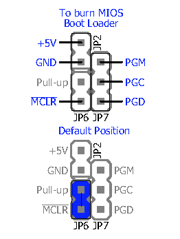
-
10 hours ago, emerson said:
Am I right in seeing that the center pin of the MIDI Out DIN should be attached to pin 15 / ground of the DB25? That one is not, I'll look to fix it. The other four from the two MIDI DINs are correctly connected (ie, MIDI In seems to be hooked up correctly, unless it relies on the pin 15 / ground from the MIDI Out DIN).
(Edit: Or is this the thing I vaguely remember where you ground the MIDI cable shield but don't attach it to one of the pins?)
Good pinout is this one:
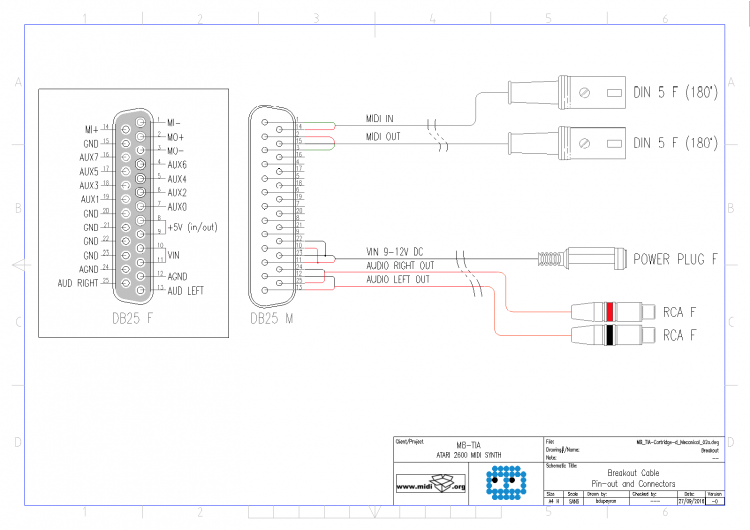
Check if IN pins are not inverted
MIDI IN pin4 connected to MI+. DB25 pin14, wire should be green
MIDI IN pin5 connected to MI-. DB25 pin1, wire should be whiteMIDI OUT pin2(center) connected to ground. DB25 pin15
MIDI OUT pin4 connected to MO+. DB25 pin2, wire should be green
MIDI OUT pin5 connected to MI-. DB25 pin3, wire should be white10 hours ago, emerson said:MIDI In isn't working, and I don't have a PIC burner for surface-mount PICs, so... not yet.
There's no specific burner for surface mount, if you've got one you can connect it like this:
10 hours ago, emerson said:Am I correct in thinking that the MIDI light staying on is possibly destructive and I shouldn't keep it powered up that way?
No it's not destructive, le led are software driven, they their own pic pins.
Do you try to do a "Query" in MIOS Studio even with this led behavor? (with MIDI In and Oout connected).
-
Just now, Keeze said:
It's already on midibox_tia [MIDIbox]?
Cheers
Yes sorry I was on an old dokuwiki revision ;)
-
 1
1
-

No display and weird sounds from MIDIBOX SID v1
in MIDIbox SID
Posted
If I remember well display is part of the CS, so it will not initialize with the firmware you use.
But maybe I'm wrong.
BR
Bruno