artyman
-
Posts
104 -
Joined
-
Last visited
-
Days Won
2
Content Type
Profiles
Forums
Blogs
Gallery
Everything posted by artyman
-
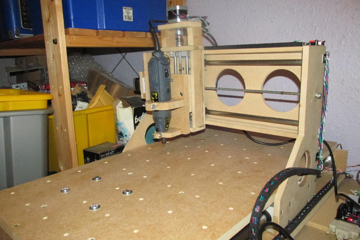
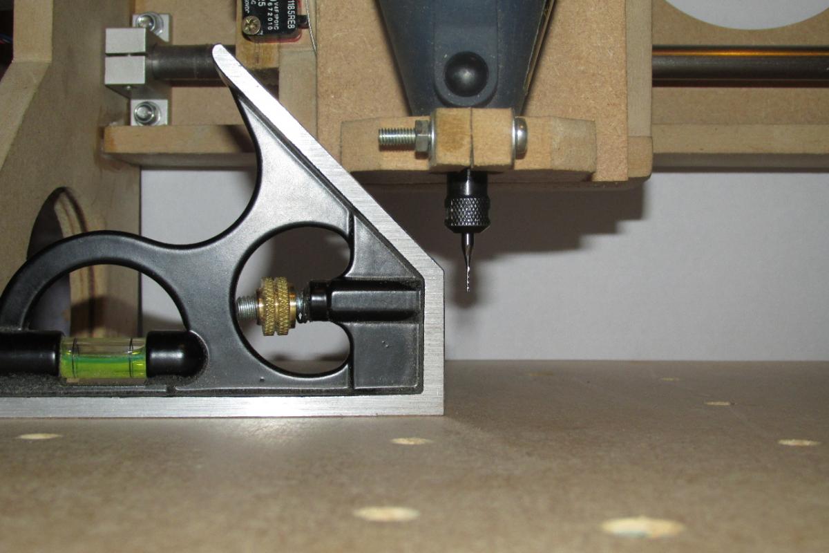
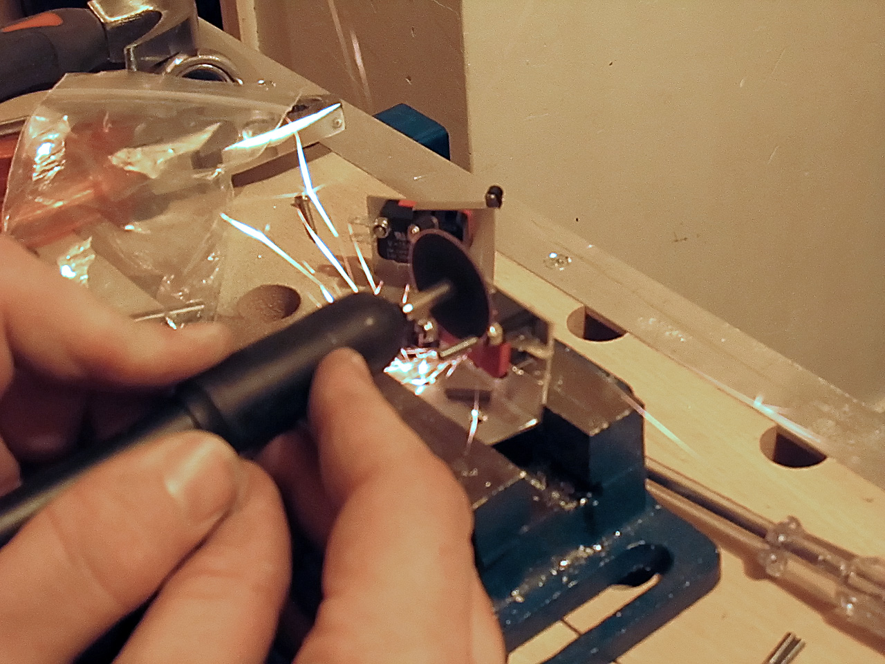
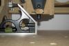
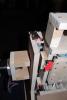
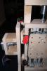
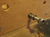
Finally, after my busiest time of the year at work... I've managed to find time to fabricate the tool mount and fit my spindle. I'm incredibly pleased... not only is the tool solid in the mount, but it's also perfectly perpendicular to the table !! :smile: :D :happy: :hyper: Next step is to buy the full version of Mach3, then I can start cutting!!!
-
Oooooooo..... new look to the forum... nice ;) :D
-
I would just like to send my best wishes to you all, of whatever faith you follow, and it's relevant holiday at this time of year. :sorcerer::santa: artyman
-
Nice pics !! :smile: Good idea on the usb hub... something I was thinking of. Also, it wouldn't be too difficult to add a switched DC input socket for the option of mains power which disconnects the usb power when a plug is inserted.
-
Aha!! That could be why the datawheel on my old Digitech GSP2101 is jumping erratically... very useful piece of info. Thank you
-
Video of the first test, after lots of head scratching during the configuration of it all...
-
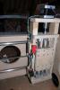
Finished wiring now.... time to power up and test !!!!


-
it's alive... It's Alive.... IT'S ALIVE !!!!!!!!!!!!! First - a home built CNC... Next - THE WORLD !!!! mwah-ha-ha-haaaaaaaaaaa !!!
-
@nILS - I don't think the problem is in the design of the board... it's a very elegant design. The problem is in trying to fit the sheer number of connectors on the back panel. The obvious answer, that people seem to be avoiding is to use the facility you have provided (header pins) and mount the connectors off-board, for example, on a daughter board. There's no reason why this arrangement should be any less stable, physically, than having the connectors mounted on the GM5x5x5 board itself, and allows the user slightly more flexibility on the aesthetic layout of the panel. Personally I prefer to have all my inputs grouped together, likewise the outputs. As for the problem of fitting 2 boards in the case, with the connectors mounted off-board, the 2 PCBs can be stacked 1 on top of the other without any problems. A USB hub could be stripped out of it's case and fitted internally, thus providing a single USB connection on the rear panel. BTW if I were to mount the USB connector off-board, which pins are the D+/D- ? I see the 5V and GND pins are marked. Finally.. Well done on such a successful and versatile board :frantics:
-
Why not mount the DIN sockets on a separate PCB and connect them to the existing GM5x5x5 board with ribbon cable 'tails' to PCB headers... then the rear panel can be arranged however the user wants e.g. the IN and OUT for each channel beside each other, or all the INs together and likewise all the OUTs? This would make the configuration easy to arrange according to space on the rear panel - 9 channels on the rear & 1 on the front. Maybe even 8 rear channels, and 2 on the front. Apologies Shuriken... just re-read your post !!:unsure:
-
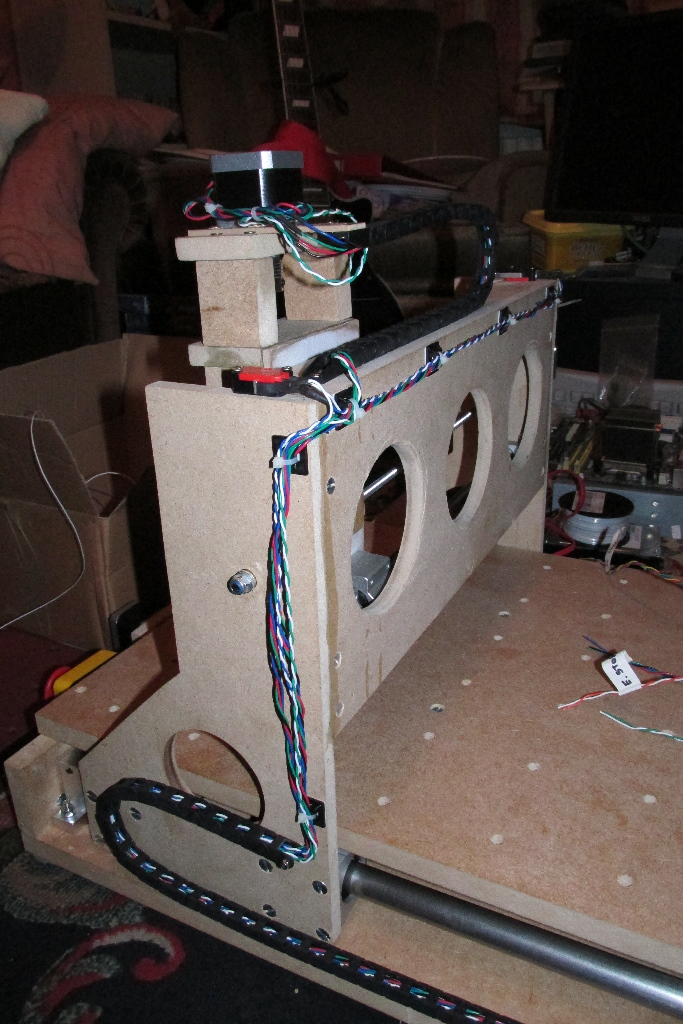
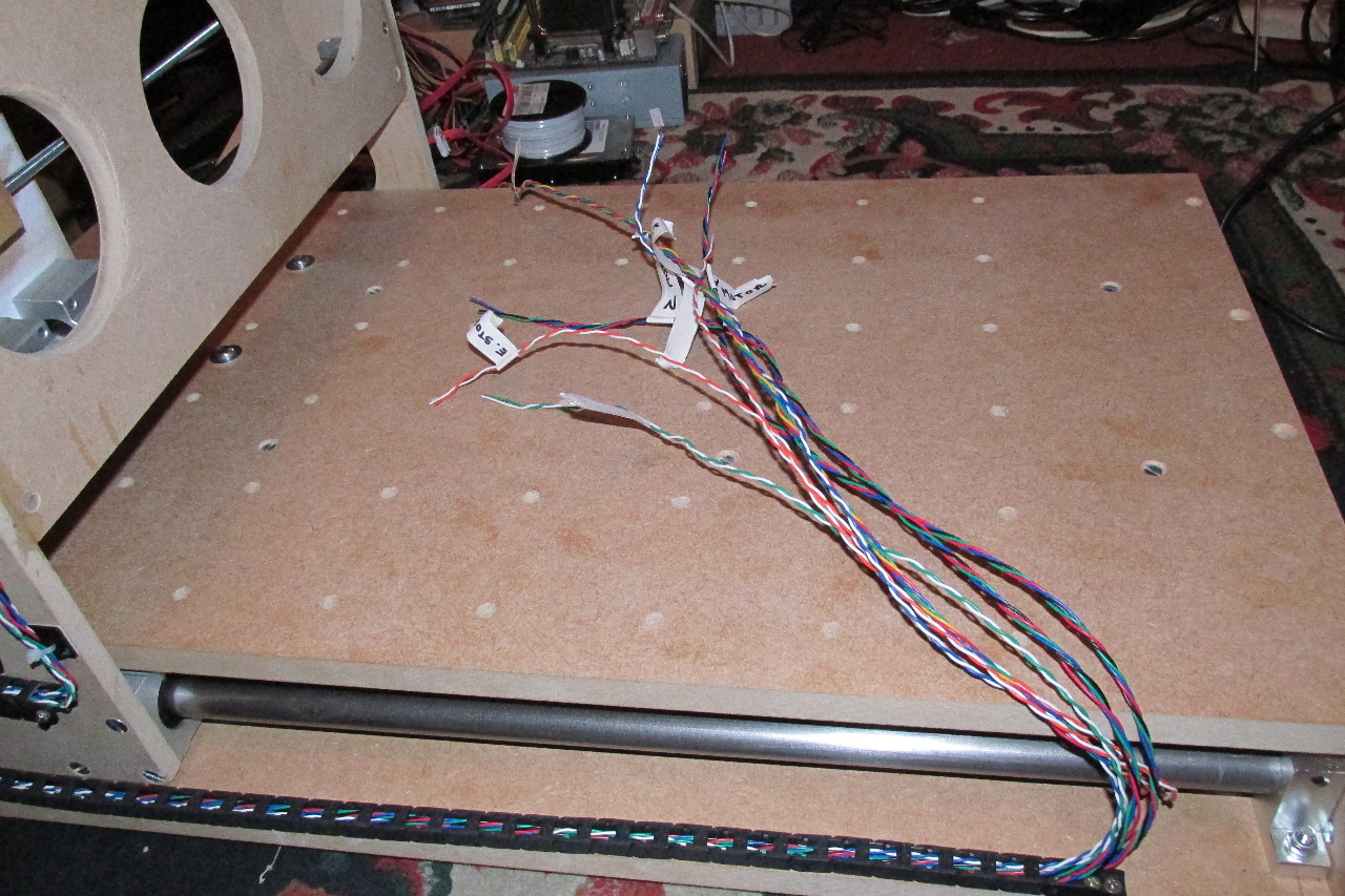
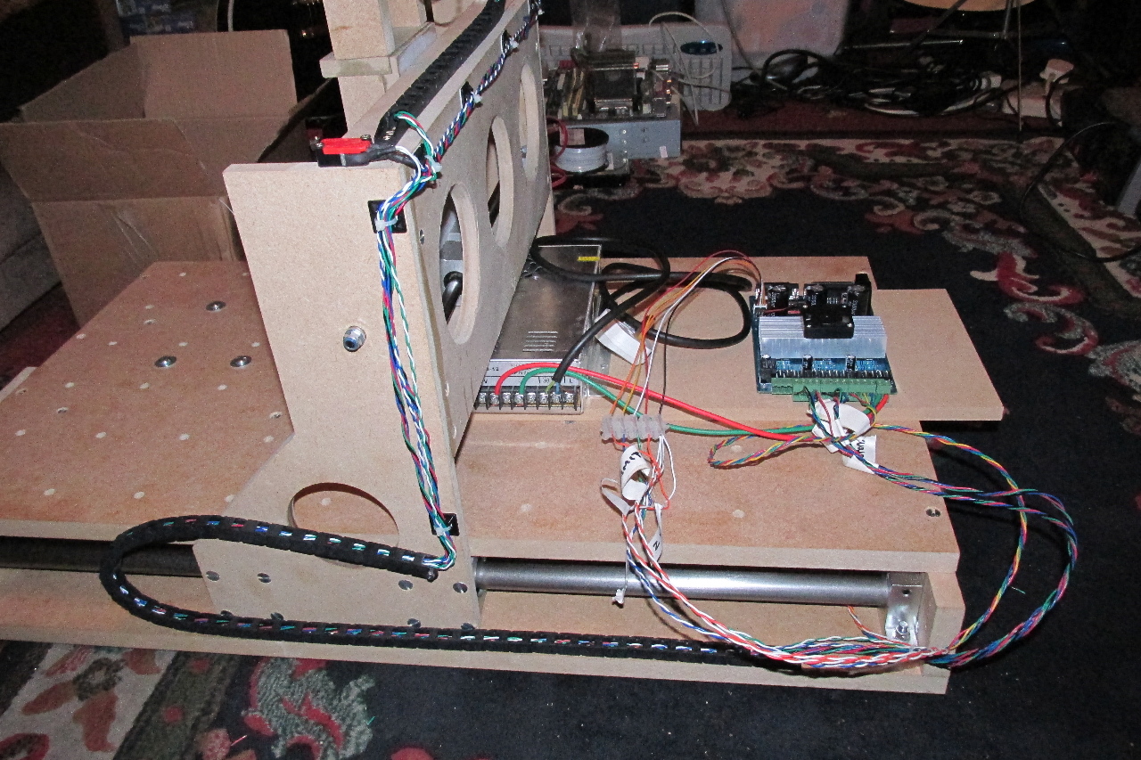
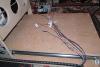
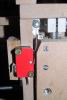
The fixed wiring on the base section (X axis motor, X limit switches & E Stop switch) is now complete.... Next is the fun part... all the wiring that feeds through the drag chains.

-
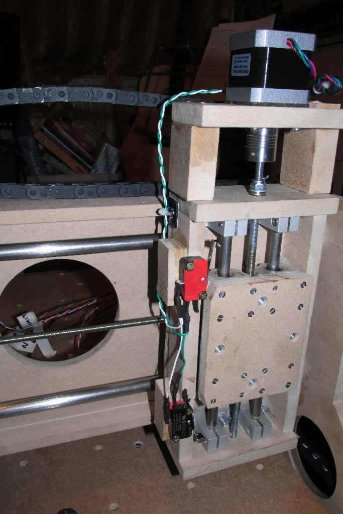
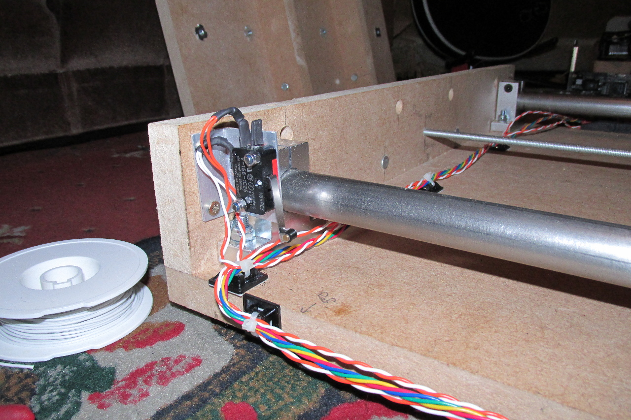
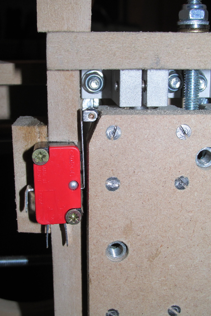
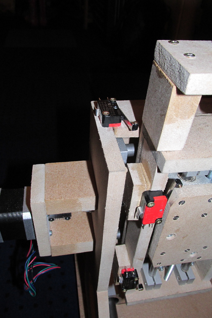
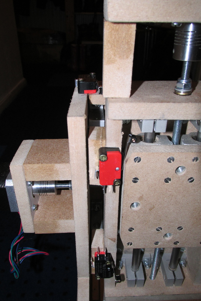
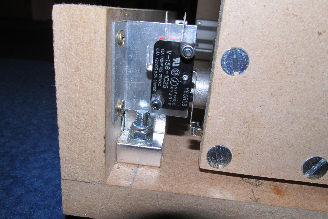
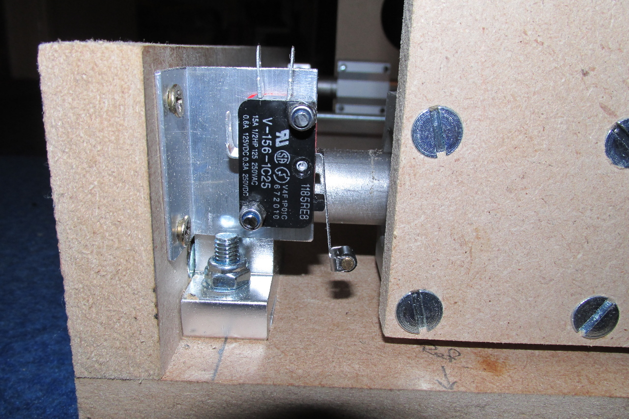
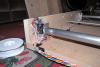
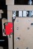
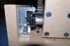
Now that I have the microswitches, and the E Stop switch, it's time, with a little help from my daughter, to fit those. The X and Y axes were an easy fit, One set screwed directly to the structure, and the other needed just a simple L-bracket to fit. The Z axis, however was a bit more challenging. Although I got subminiature microswitches, they were too wide for direct actuation as the other axes are arranged, so a little inventive thinking was called for. As I had roller actuators, I decided to cut chamfers on the Z-slider, and mount them inline. This also meant that i had to file a notch in the side wall so they wouldn't interfere with the tool mount (when fitted) as it passed over.


-
Happy Birthday TK. :sorcerer::frantics:
-
Typically, while visiting the parents... my dad found and gave me a pillar drill (drill press) that he never used..... just after I've needed it most :S
-
As TK described for the SFBs to be global, you need to set up your 'global' buttons to be the same in each bank.
-
CNC is cracking on now.. just the limit switches to fit, then wire it up and start motion testing it. ;D
-

-

-

Hehe, yeah, I have also thought of those kinda money sinking activities... Rather intriguing stuff that is... I remember way back at school we had a portable CNC which was extremely expensive said the teacher, but all it could really do was engrave letters in wood. I should build a real one and show em :P But dude, keep pics and vids comming. Nice work!
-
-
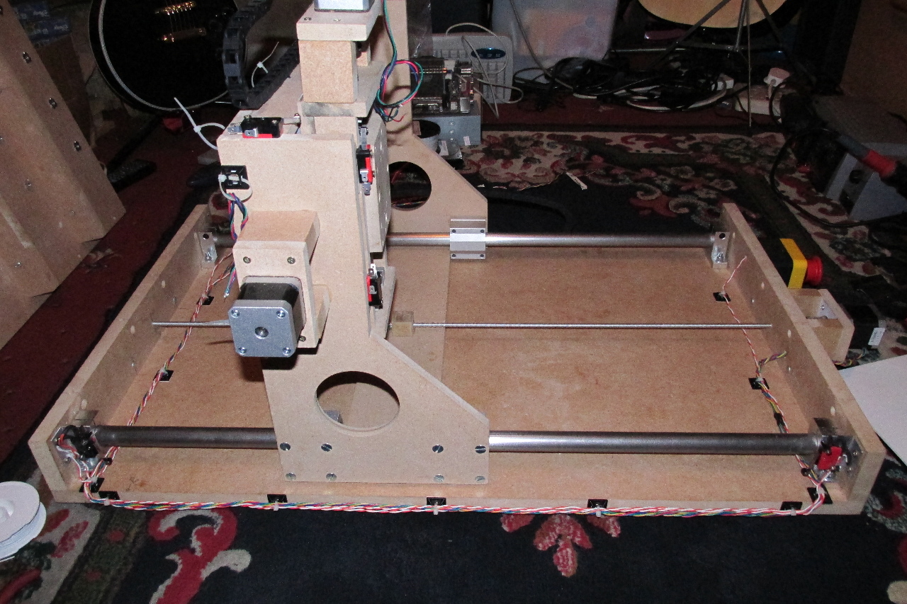
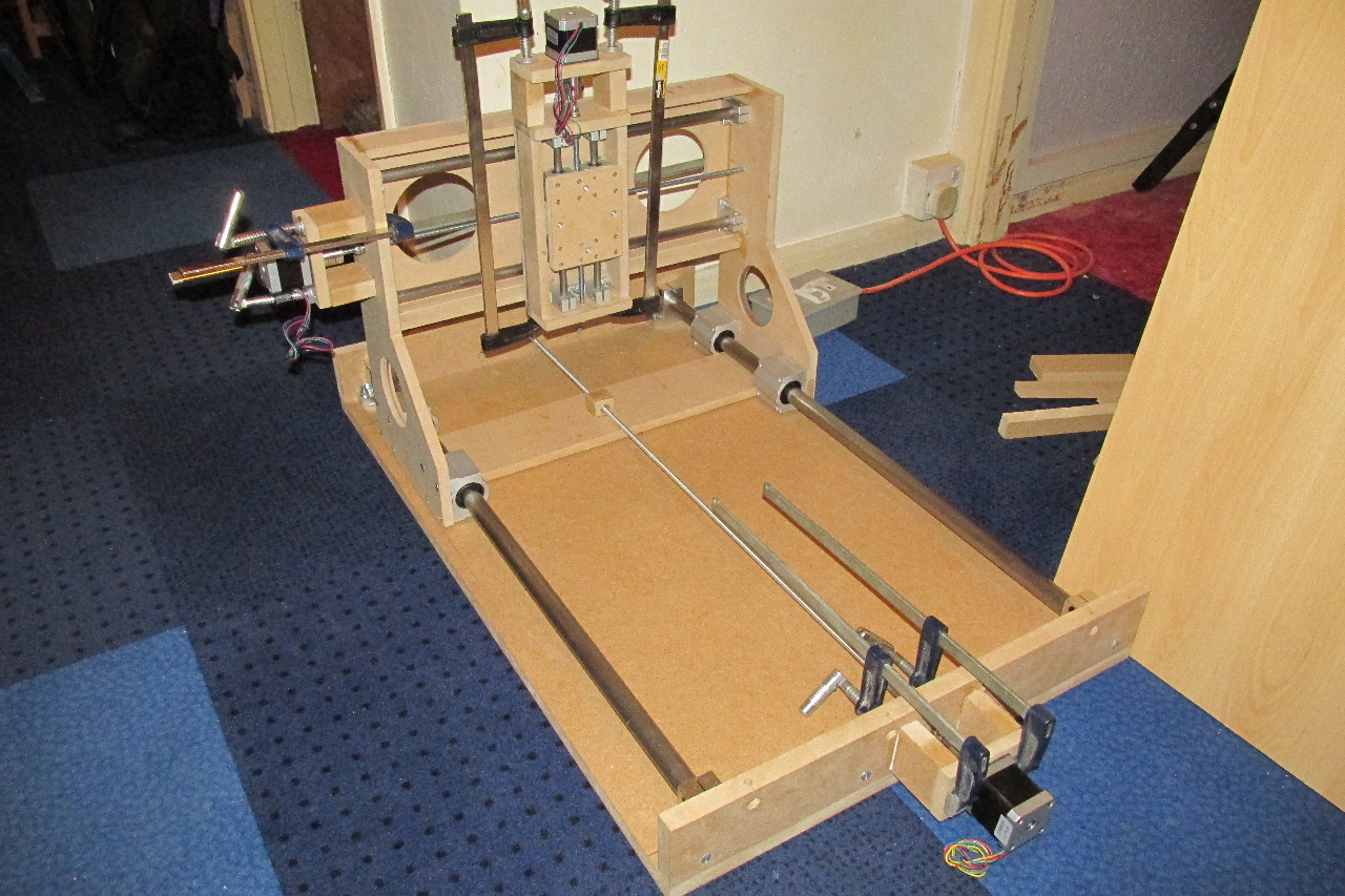
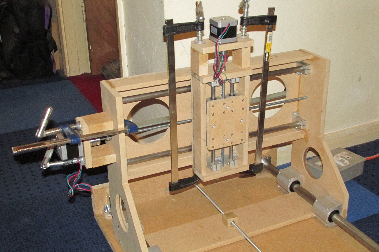
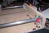
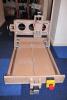
The end is just about in sight..... Stepper motors are now fitted. Just the limit switches to fit, then wire it all up!!!..... .... and hope it all works !!

-
Gotcha !!.. I was wondering if the USB ground needed to be connected as well. Cheers
-
The whole thing will be powered from a 12vDC input with 5V derived from that. The USB power option will be disconnected. The plan there is to only connect the D+ and D- from the USB socket via a pin header on the PCB. The ground will come from the common PSU ground via J7.
-
Hi, I'm in the final planning stages of a 2-core MBLC and intend to use a GM5 mini PCB for USB connection to my PC. reading up on the GM5 module, it says the headers at J6 can be used for direct digital connection to J11 (core). Does this mean I can leave out the opto-couplers on both the GM5 and the core? There will be no external MIDI connections, as this is planned as a completely self-contained unit. Many thanks in advance
-
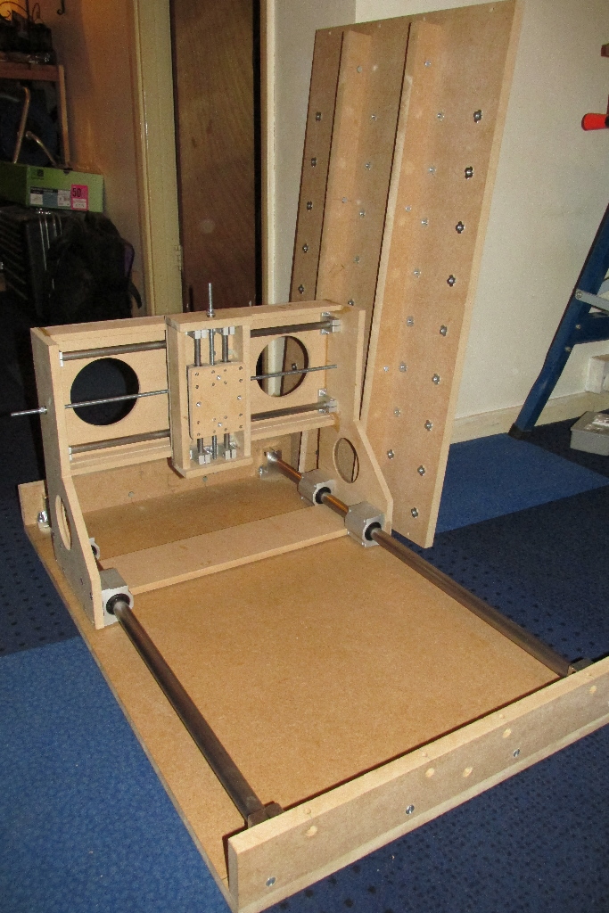
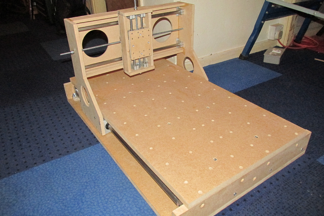
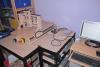
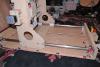
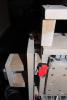
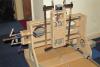
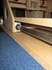
Well.. after a busy period at work, and looking for a 'new' car, I find myself back on leave, and time to do some more work on this. Now that I've dry fit the pieces of the base section, it's time to drill and bolt everything down. Also at this time I've drilled a grid on the table and fitted T-nuts to the underside for screw-in clamps. Note also the 2 braces on the underside of the table to reduce any flexing. These additions to the original design, fortunately were possible without interfering with the bottom brace of the gantry EDIT Also showing detail of the thrust bearings used on all of the lead screws.


-
Hear, Hear... I'll second that !!! ..and third it as well !! :thumbsup:
-
I'm not sure how well it will perform with metals, though I'm hoping it will be able to cut Aluminium and Brass. It will be the subject of some very careful experimentation. :thumbsup: @Hawkeye - thank you, I'm hoping all the effort will be worth it.