electrodancer
-
Posts
176 -
Joined
-
Last visited
-
Days Won
8
Content Type
Profiles
Forums
Blogs
Gallery
Everything posted by electrodancer
-

Red and black sammichSID replica w/ 2xSID emulators
electrodancer replied to Sgw32's topic in Fleamarket
would like a set of pcb's -
also have a stm32F4 discovery board link to pics: https://www.facebook.com/groups/synthdiy/permalink/10158778005481313/
-
Could not upload pics for some reason....send me a mail please
-
Selling: build and fully working TPD Track position display i have made a eurorack panel for it and have some extra front and back panels also selling a BLM pcb 45 euro for the set wil not sell seperate mail me at: vincentvdwiel@gmail.com IF interested im not much on this forum
-
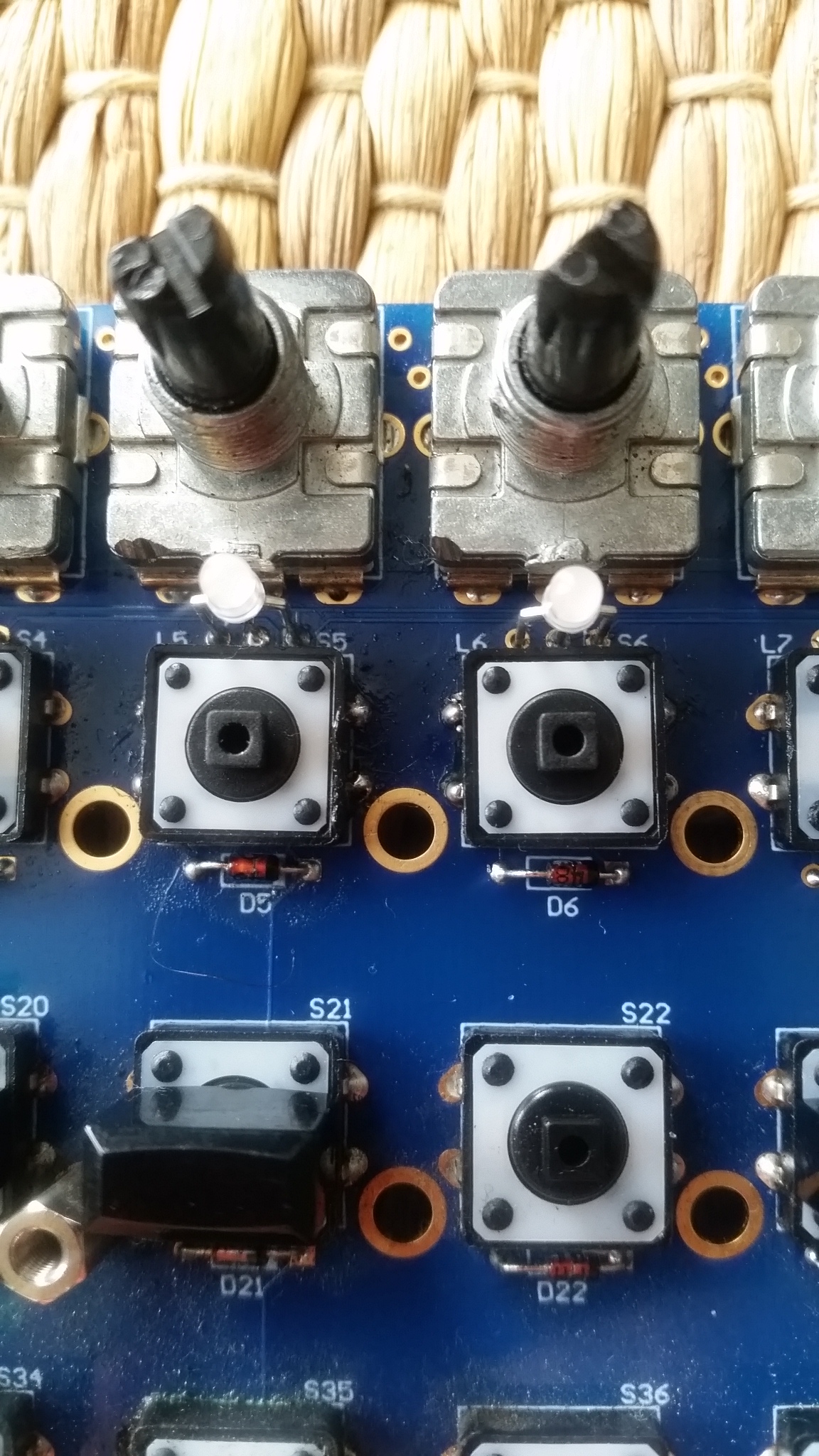
did some beeping again.....as this guy...himself replaced the menu switch....he probably damaged a trace ..... there was no connection between d21 and d35 ..... so its all working now thanks guys ! wilba_mbseq_pcb.pdf
-
okay thank you ive been testing the switches....they give a beep if i put my meter on them A-A gives a beep and B-B gives a beep and A-B gives a beep when switch is pressed...... one other thing ive noticed......with my own seqv4 the step led lites up green when i turn the encoder....with this board the led does not light up when i turn the encoder so that is weird
-
hi Peter thank you for helpling me (again you are my forum hero !!!)....but even with the schematic i can not find it. hoping you can help me a little more....this is what ive cheked so far: if i put my meter in beep mode and have one pin on the bottom left pin of Step switch 5 and the other pin on U2 pin 11....then i get a beep if i press the switch the same goes for step switch 6 bottom left pin to U2 pin 12 ...also gives a beep..... so this should be good right ? ive also replaced the duo color leds and also both 1n4148 diodes...but it did not help what other things can i check ? with kind regards, Vincent
-
ok traced them down to U2...and that side is okay....but still can not find the fault.....are the switches connected to a groundplane or something ? because he ripped off some solder pads
-
hi people im hoping someone can shine a light on this problem im having with a midibox seq4 it has the wilba control surface (its not the new seqv4+) stepswitches 5 & 6 are not working (the guy who owns it tried to replace them...but he really did a grimm job soldering i cant really see where the traces are going and to what ic these two switches connect (it can probably be fixed with a wire but i need to know to what ic and pin they are going) any help is welcome, cheers Vincent
-
New eurorack modules from midiphy - preview
electrodancer commented on Hawkeye's gallery image in Members Gallery
 looks cool guys !
 -
 Fancy !
 -
midibox stuff pic programmer, core, lpc board LCD
electrodancer replied to electrodancer's topic in Fleamarket
its all sold ! -
hi guys when i send a gate to the GATE input on my v4+..notthing happens Do i need to set anything in the menu ??
-
how to get gates and cv working for the seqv4+
electrodancer replied to electrodancer's topic in MIDIbox SEQ
solved....it was a missing jumper on de linedriver transmitter board -
hi there thank you it was indeed the jumper on the transmitter....now i have power on the aout board cv, gates and clocks are working !! another question i have is : is it possilbe to also connect the (old) TPD ? in my seqv4 i had it after the doutx4..... but now i see there is something different in the hw file (the option to choose the midiphy tpd) now TPD enabled 3 is set...and normally with the seqv4....TPD 2 would be set......would it even be possible to connect the old TPD? ################################################## # Optional LED Track Position Display # See also http://www.midibox.org/dokuwiki/doku.php?id=tpd_pcb ################################################## # set to 1 or 2 to enable the relative track position display # 0: TPD disabled # 1: TPD enabled - columns are cathodes, rows are anodes # 2: TPD enabled - columns are anodes, rows are cathodes # 3: TPD for midiphy frontpanel enabled - columns are anodes, rows are cathodes, inversion TPD_ENABLED 3 cheers Vincent
-
so on the old one this should be already jumpered?
-
i have the old linedriver receiver board....ill build the new one from midiphy and try again
-
also using the new lindriver transmitter...... and the old linedriver receiver board
-
my setup now is : seqv4+ with new lindriver transmitter but on the other end i have the old linedriver receiver that might be the problem aout-ng is powered from my eurorack +12 and -12 volt and it needs power from the sirio chain (i think)
-
hey there....im trying to get my aout-ng gates and clocks working.... ive set the shift registers in the hw file (10 and 11) but no gates clocks and no cv...also the power led on the aout-ng does not light up with the seqv4+ (and it does light up with my seqv4) tips are welcome.... cheers Vincent
-
how to get gates and cv working for the seqv4+
electrodancer replied to electrodancer's topic in MIDIbox SEQ
thanks ...that makes sense ive followed up on the link....and set the shift registers but still no cv gate or clock also the led on the Aout-ng does nog light up when i connect the seqv4+ (and it does light up when i connect the seqv4) so i think there is no power over the 25 pin cable ?.. cheers Vincent -
hi there...ive build the seq v4+ but now i can not get the CV (from Aout-ng) and GATES and CLOCKS (from dout board) working i have the (new) linedriver transmitter inside the seqV4+ and i have the (old) lindriver receiver on the other end of the cable i have a Aout-ng board and a doutx4 connected to the receiver (clocks, gates and cv were working on my (old) seqv4...now im trying to get this working with my new seqv4+ what ive tried: inspect the linedriver module set the si jumper on the lindriver transmitter (it is there on my old seqv4) set the correct Aout board in the menu ive tried to assign the shiftregisters to the same numbers and pins in the hw-file as i did with my old seqv4....but this gives only messed up leds. can some one help me with this ?
-
midibox stuff pic programmer, core, lpc board LCD
electrodancer replied to electrodancer's topic in Fleamarket
-
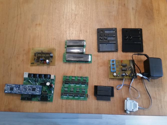
hello ive got some older midibox stuff that i do not use anymore. maybe somebody stil has some use for it 1x pic based core 1x lpc based core (with seqv4 software) 2x din R5 board 1x PIC PROGRAMMER (with printerport connector and power supply) 1x pic18F4520 1x pic18F4620 1x pic18F4685 2x panelset (front and back panel for the TPD track position display 3x LCD display selling the whole lot in one go for ....20 euro
-
thanks.....got it working now...!!! it was 4 shift registers (ive tried 5 but that didnt work) thank you !!