

jjonas
-
Posts
422 -
Joined
-
Last visited
-
Days Won
24
Content Type
Profiles
Forums
Blogs
Gallery
Everything posted by jjonas
-
From the album: miscellaneous
-
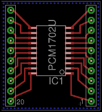
Shuriken: I don't know, I just needed a component that is of the same size as TLV5630 (SOIC-20), and that's what I found in the component databases I had installed. latigid on, here's the same circuit with GND.
-
From the album: miscellaneous
-
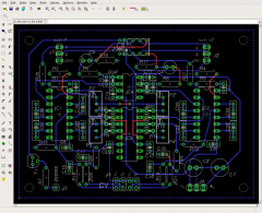
Hi, I've continued to troubleshoot this problem, which still persists. I couldn't find any shorts anywhere, so I desoldered the chip and put a new one in its place, though not on the AOUT_NG board (some of the pads were damaged while desoldering) but on a daughterboard that I got from OSHpark. I soldered this onto the AOUT_NG with wires, and tried whether the new chip gets hot. It didn't, not even after a while, so I started recalibrating the AOUT_NG board. All went ok, calibration was finished successfully without the chip getting hot. I guess it took an hour or something. Now I attached the seppoman SSM2044 pcb that I got from OSHpark as well, one that I made based on the PCB picture and the schematic that are available on the wiki, and started calibrating it with MB6582. Everything seemed to work, cutoff was ok, only right channel resonance wasn't working. At this stage the chip was still ok, i.e. not hot. When I finally found what was wrong with the right channel's resonance (C20's legs were soldered to the same point), at the same time I noticed that the new TLV chip on the daughterboard was getting hot, and when I tried whether the filters were still working, they weren't (I had been inspecting the filter PCB for mistakes for some time). TLVs are kind of expensive to be fried like this while troubleshooting, so I'm not sure what the best course of action would be. I have one more chip left, it's already soldered onto a fresh AOUT_NG board, I thought I'll test it by attaching the complete and calibrated board to the MB6582 and leaving the power on for several hours, and if it's still working, maybe at least the AOUT_NG is ok. After that the decision of whether to use the DIY SSM2044 board or something else is open. If people have ideas for external filters to be used with MB6582, other than self-drawn PCBs, I'm all ears :-) (Giving up on the SSM2044 would be ok for another reason too – like I found others pointing out in another thread – namely it cuts the bass when resonance is turned up.) I don't know if anyone has the time to check the filter PCB (in case that's the culprit), but anyway here it is (I'm not really asking anyone to comb it through). It's more or less a direct copy of seppoman's board from the wiki, though it's possible I've added a few mistakes :-) Anyway for me the mystery is that for a while everything was working, and as far as I could tell, voltages were ok (on both AOUT_NG and the filter PCB)
-
From the album: miscellaneous
-
From the album: miscellaneous
-
Hi, if you're just asking about whether to have one header for several destinations, or a separate header for each destination (which is the level I'm able to give any advice on), I would have several headers, one for each destination. For example if you have four 5VDC destinations, you could - instead of feeding all destinations from one "master" 5VDC header on the PSU board - have four 5VDC-GND headers on the PSU board (i.e. four times two pins) that are fed by the "master" 5VDC (and GND) source on the PSU board. I don't know how many destinations you'd have, but the more you have, the easier it becomes to troubleshoot power supply problems if each destination can simply be unplugged (without need for de- and resoldering, for example), to test one module at a time.
-
Just to follow up quickly on setup, I'm using LPC17 and an external DCA based on TDA1543.
-
That's mellotron cello, isn't it! :-) I've used the sample player for playing mellotron samples for a few years, and when I read your message from 8 April about distortion, I thought the problem was much bigger than it turned out to be when I now listened to your attached sample: for me the sample player has always behaved like this, i.e. I've noticed that it breaks down a bit, or there's some little crackle like in your attached sample, but I've never thought it's that much of a problem.
-
You're right, you need only two DINX4 and one DINX2 – with three DINX4 you'd just leave one half of the third board empty. But for most people doing a modular build, three DINX4 is the way to do it, as DINX4s (but not DINX2) are available at SmashTV or Mike's shop.
-
Hi, and welcome to the forum! Just a partial comment: the number of DIN/DOUT modules you need doesn't depend (except for the four buttons with which you select one of the 2-4 cores) on the number of CORE/SID modules in your build, but on the kind on control surface you want to build. For full control surface you will need three DINX4 (for all the encoders and buttons) and two DOUTX4 modules (for all the LEDs). See scroll down to section "Hardware costs" and under the headline "Complete Control Surface" here: http://www.ucapps.de/midibox_sid_manual_hw.html For connecting the buttons and encoders, see: http://www.ucapps.de/midibox_sid_cs/mbsid_v2_din_default.pdf ..and for connecting the LEDs, see: http://www.ucapps.de/midibox_sid_cs/mbsid_v2_dout_default.pdf Regarding banksticks, in practice you would need at least two: one for Ensembles (=overall settings that you want to save) and another for saving your patches. For the longer run I would choose 24LC512 over 24LC256 to double the amount of patches you can save per bankstick, but that's just a personal choice :-) You don't need styroflex caps for the SID; for the 6581 you can use 470pf ceramic ones. (See http://www.ucapps.de/midibox_sid_manual_hw.html, section "SID chip selection").
-
Here are the settings with which I managed to program the bootloader onto the chip:
-

Settings for Elnec SmartProg2 to program PIC18F4685.
jjonas posted a gallery image in Members Gallery
From the album: miscellaneous
These are the settings I used to program MIOS bootloader onto a PIC18F4685 with Elnec SmartProg2. -
Hi, thanks for all the replies, I can now report success! I followed TK's advice, but in addition to that (when comparing to the screenshot I originally provided) I still needed to tick the boxes for "Programming parameters [x] Configuration bits" and "ID Locations [x] Ignore Microchip recommendation to let most Significant nibble on each ID be Fh" in order to make it work. As regards Tim's advice, reading the SmashTV chip didn't affect the programming configuration settings, but programming the blank chip with the stuff read from the SmashTV chip with the correct settings worked as well. I also tried changing the ID8 to 01 to check whether MIOS Studio is able to communicate with it using device ID 01, and it worked too. I took a screenshot of the correct settings and was going to upload here it for future reference, but I'm now at work, and the image was too big (<2Mb) for upload, so I'll upload it later when I get home and have scaled it down.
-
Hi, I tried them all, programming was successful every time, but MIOS Studio was not able to communicate with the chip (I tried with device ID 00). There were a few differences though: with "HS" my PSU (with a 3-number display: 0,00) drew 10mA, with "HS-PLL enabled freq=4xFosc1" it was 30mA, and with "INT RC-CLKOUT on RA6, Port on RA7" it was 10mA. With all the other options the PSU didn't appear to draw any current. (The functioning SmashTV chip draws 30mA, FWIW.) Regarding the image link I posted above, the parameters I used to try different oscillator configurations are as shown there, except for these: - Section "Programming parameters", all boxes ticked. [x] User Program memory and ID locations [x] Data EEPROM memory [x] Configuration bits - Section "ID Location", all values 00, plus box ticked [x] Ignore Microchip recommendation to let most Significant nibble on each ID be Fh. - Section "Configuration bits": MCLRE = 0: RE3 pin enabled, MCLR pin disabled. (I changed this because what I take to be the equivalent tick box in the PICkit2 GUI programming guide was also unticked.) I erased the chip every time before programming it with other settings. After trying all the oscillator options, I also programmed it without configuration bits (with just "[x] User Program memory and ID locations"), but to no avail.
-
Hi, thanks for the reply! SmartProg2 GUI offers the following oscillator options, any idea which one of them is the correct one? Oscillator [FOSC3:FOSC0]: 0000 = LP 0001 = XT 0010 = HS 0011 = EXT RC-CLKOUT on RA6 0100 = EC-CLKOUT on RA6 0101 = EC-Port on RA6 0110 = HS-PLL enabled freq=4xFosc1 0111 = EXT RC-Port on RA6 1000 = INT RC-Port on RA6, Port on RA7 1001 = INT RC-CLKOUT on RA6, Port on RA7 101x = EXT RC-CLKOUT on RA6 11xx = EXT RC-CLKOUT on RA6
-
Hi, I have an 18F4685 chip (it says PIC18F4685 I/P on it) which I'd like to program with the MIOS bootloader. (I figured this is one of the places where it makes sense to post this.) I'm using Elnec SmartProg2 programmer which supports the chip, and according to the Elnec GUI programming was successful. However, MIOS Studio is unable to communicate with the chip. It's possible that the only problem is with device ID, but I've tried ID 0-20 and 120-127, and don't see what the logic I should use to try any of the ones in between would be... I've tried programming with ID1-ID8 as 00 (instead of FF, the default), but that didn't help. I'm sure my connections are correct, I've tested them with a chip I've bought from SmashTV, and communication works fine. Here's a link to a screenshot of Elnec GUI's default settings screen, any advice on the correct settings..? https://www.flickr.com/photos/68202862@N03/13710200005/ These are the default settings (minus the tick in the 'User program memory and ID locations)' box). I've tried setting ID1-ID8 as 00 (plus ticking all of the 'Programming parameters' boxes), but while attempts have succeeded in terms of Elnec output ("Programming device OK"), MIOS Studio is not able to communicate with the chip. Is there something that can be done with these Elnec settings, or should I use TEST SW2 from the midi debug guide (at the end of the page)? Or something else..?
-
Hi, I've recently built myself an AOUT_NG which I've been calibrating. I noticed that the TLV5630 gets very hot, so that after 3 seconds you have to remove your finger off of it in order not to get burnt. I noticed this only after 20 minutes of fiddling with MBSID settings, and during that time I managed to get the frequency filter working (not yet resonance; I'm using a self-made seppoman SSM2044 PCB). So it didn't burn out the chip in that time, and it seems to be working as well, so I'm asking whether it's normal that the chip gets very hot. The AOUT_NG board draws 560mA (and the LED lights up normally), when it's attached to the MB6582's J6_CORE4 and nothing else – to me that sounds like a lot, but I'm not sure how analog synth stuff is supposed to operate :-)
-
I'm confused about pattern length and synchronization
jjonas replied to jjonas's topic in MIDIbox SEQ
I think I get it now. I thought I'll summarise what I've learned below, I hope someone will find it helpful (and not mistaken :-) I have two tracks, one 16 steps long and one four steps long. Measure (Options menu, 1/10) is set to 16. G1T1|---- ---- ---- ---- ---- ---- ---- ----|---- ---- ---- ---- ---- ---- ---- ----| G2T1|---- ---- ---- ----| If there's no guide track, G1T1 will play to the end (all 16 steps) and then start from the beginning, while during that time G2T1 will repeat four times. If you set measure to 8, only the first half of G1T1 will get played before it starts from the beginning, and during this time G2T1 gets played twice. If you then set guide track to G2T1, it will override the measure setting (Option menu, 1/10), and the loop length will be whatever is the length of G2T1 in the pattern that is being played. Let's say you have two patterns, 1:A1 and 2:A1, where all tracks (including G2T1) are 16 steps long. When these patterns are playing and guide track is set to G2T1, the loop will be started from the beginning after 16 steps, because that is the length of G2T1 in the pattern 2:A1 which is being played. If your G2T1 was 20 steps instead of 16, G2T1 would – we're still assuming guide track is set to G2T1 – play to the end, all 20 steps, and then restart. Those tracks that are shorter, let's say 16 steps, will run their whole length, and then play the first four steps from the beginning of the track, at which point (16 + 4 = 20 steps) the guide track set to G2T1 will force all tracks to restart. This is what confused me in the beginning – that the other tracks will just restart from the beginning while the longer guide track will run its course (and once the guide track finishes, all tracks restart). I already thought I had gotten it working because my longer track was a bassline and the other tracks were drum stuff that were always the same, so I didn't notice that the drum tracks restarted from the beginning. So let's say I wanted to have a 4-step-long drum break in the middle of "normal" 16 step tracks. The way this can be done is you set guide track to G2T1, the drum track (in my case). When G2T1 plays patterns that are 16 steps long, nothing special happens because all the other tracks are 16 steps long as well, so it works the same when you use Options menu to set the Measure to 16. Here's what I have. A bassline track (G1T1, pattern 1:A1) which is 16 steps long, and a drum track (G2T1, pattern 2:A1) which is 16 also steps long. G1T1 – 1:A1 |---- ---- ---- ---- ---- ---- ---- ----|---- ---- ---- ---- ---- ---- ---- ----| G2T1 – 2:A1 |---- ---- ---- ---- ---- ---- ---- ----|---- ---- ---- ---- ---- ---- ---- ----| After this sequence has played once, I want to have my four-step-long drum fill. For this I need two more patterns, one with my fill (2:A2) and the other (1:A2) with nothing in it: G1T1 – 1:A2 |---- ---- ---- ---- ---- ---- ---- ----|---- ---- ---- ---- ---- ---- ---- ----| (nothing on this track) G2T1 – 2:A2 |---- ---- ---- ----| (drum fill track) The reason I need an empty track is that I just want the fill with no bassline in the background. Of course 1:A2 too could have something in the first four steps, and they would get played; anything coming after four steps would be left unplayed though, because it is G2T1 which is set as the guide track, so it determines how many steps in each pattern gets played. The song sequencer, which plays different patterns in the order you've determined (along with other commands), would look like this: Song Pos Actn G1 G2 1 A1 x1 1:A1 2:A1 <- these two patterns (1:A1 and 2:A1) are 16 steps long, and 2:A1 is the one that determines measure. 1 A2 x1 1:A2 2:A2 <- here 2:A2 is the determinant (G2T1 within it, to be exact), and it's irrelevant whether 1:A2 is 4 or 16 steps; only the first four will play. If 1:A2 was only two steps 1 A3 Jump -> pos. A1 long, it would be played two times during the time 2:A2 plays through its four steps. I now understand the flexibility of guide track, and I think it's more flexible than the tracker style implementation that I originally was looking for. Super! :-) -
I'm confused about pattern length and synchronization
jjonas replied to jjonas's topic in MIDIbox SEQ
Hi, I tried this with the song I was working on, it worked, but today I tried to use it on another song where the setting was a bit different, and I failed to get it right, so I guess I don't really understand the concept of guide track; apparently there can be only one guide track per song? I did get the other song right in the end too, but I can't say I really understand why it started working. Could you explain a bit further what the "normal operation" of the MBseqv4 is, and how guide track changes that? And could other people write about how they use dividers, track lenghts, measure, and make it all work together etc..? For a beginner that would be perhaps the most beneficial approach, and then when you've learned enough you can deepen your understanding with the manual, but for a beginner it's kind of tough to survive just based on the manual. I've read it and tried to look for the relevant sections for solving my problems, but I haven't really been able to see the big picture from all the details. Apparently you can have lots of tracks with different lenghts & dividers run in parallel, but somehow they have to match the overall measure, right? What in your (=the people who use MBseqv4) opinion is the most sensible way to organise all that? Thanks! -
Hi, I've recently completed an MBSEQv4 and I'm trying to teach myself to use it. What I've not understood this far is pattern length and sychronization. The user manual section on the Options menu gives some hints, but can't say I completely understand what it tells me about pattern synchronization. I have a song where most of the patterns are 48 steps long, on G1T3, channel 3 (this far the whole song uses only one track and one channel). If I recall correctly how I first encountered the problem, in phrase mode all my patterns played fine individually, but in song mode they were changed each 16 steps. I found that altering the measure leghth in the options menu helped (I set it to 48 steps per measure). Now most of my patterns play fine also in song mode, but a few of my patterns are 72 steps long, and they seem to be forced to the uniform length of 48 steps per measure, so the 72 steps long pattern is cut short (judging from the running step position number on the right LCD. BTW the position indicator resets after 48 in phrase mode too, it just doesn't seem to affect how the pattern is played). And if I play just two patterns of different length, first 48 steps, then 72 steps, in a looped sequence, it doesn't play as I thought it would. Is there a way to have patterns of different length play in song mode without being forced to a uniform measure, or do I just have to shorten all my patterns to something that all the pattern share, in this case 24 steps per measure? Lengthening shorter patterns with looping would be ok, but a longer pattern that cannot be looped (because the end part is different from the beginning part) would have to be cut into several separate patterns, and oversight becomes more difficult. I think I tend to look sequencing from the tracker (ScreamTracker etc.) point of view, and thought that I can just make patterns of whatever length, save them, and put them one after the other, and they will be played as individual patterns in the sequence I have determined. Is there such an option with MBSEQv4, or some other way to solve the problem I have? In case it's useful to know, my Options setting are as follows: 1/10: Track synchronisation steps per measure: 48 2/10: Pattern change sync change considered each 48 steps 3/10: Pattern change sync disabled Options 4-7- disabled 8/10: Paste and clear button will modify only steps 9/10: Initial CC value for Clear and Init is 0 10/10 If Live function, matching received MIDI events will: Do nothing EDIT: Or if I put the matter more concretely: If I have to patterns, A1 and A2, with A1 being 16 steps long and A2 being 8 steps long, how can I make them run in song mode so that A1's length is 16 steps and A2's length is eight steps (as I have determined and saved with each pattern), instead of the shorter pattern getting played twice? I've tried to do this in practice, but not only does A2 get played twice, somehow also the A1 pattern gets messed up (not starting from the beginning) in the song mode, where song pos. A1 is [ G1 1:A1 x 1 ], pos. A2 is [ G1 1:A2 x 1 ] and pos. [ G1 1:A3 – Jump to A1]. Also step view shows the strange behaviour. Which setting do I have to change?
-
Hi, I've been thinking about building an AOUT_NG and a Seppoman filter, and have a few questions before I start. I'm using a Meanwell RPT-60B as the PSU for MB6582, it provides all the necessary voltages (at the moment I'm bringing in 5VDC-GND and +12VDC-GND), though when I built the MB6582 I didn't bring in the -12VDC as I didn't need it then (also the C64 PSU secondary side cable that I used had only four wires in it). However, now I think I could replace the C64 cable with a 5-wire cable and a 7-pin DIN plug to bring the -12VDC into MB6582 as well in one of the extra wires, and then feed the AOUT_NG and the filter module via the DB25 connector in the back of MB6582, instead of another external PSU. Assuming this is a sound plan, the question – based on Wilba's base PCB picture – is: of the seven poles in MB6582's power socket (J1), is it so that only five are connected to something (five and not four, because the incoming 5VDC seems to be connected to two poles), and the remaining two are not connected to anything else than the solder pads, i.e. it's safe to bring in -12VDC to either of them and just take a wire from there to the DB25..?
-
I don't know if this helps at all, but I flashed a few xpressos last week and got a timeout error message, too. Not the same one as in your screenshot, but then again I'm probably not using the latest version (I have 4.2.3_292 from May 2012). I'm on Ubuntu but didn't have success with the GNU/Linux version of the IDE last year when I tried, so I tried using the Windows version on Virtualbox instead. That worked, but only after fiddling around with the USB connection. Maybe this is not what your problem is, but perhaps this comes up in a search for someone else later, so I'll write it here nevertheless. 1. Start the program and connect the xpresso to the USB. 2. On XP virtualbox there is a USB device icon in the bottom right. Right-click that and you should see that the xpresso board is detected as an "unknown device". Select it to mount it. But if you now try to flash something onto it, you will get a timeout message. (This presupposes that your virtualbox USB is working normally, I don't remember how to do it, but I remember I had difficulties with it.) 3. Unmount the device in the USB devices menu. 4. Now if you check the menu again immediately, it should list a "Code Red Technologies LPC-Link Probe". Mount it, and you will be able to flash the bootloader onto it. For some reason you need to go through the first unsuccessful flash attempt with the "unknown device"; without doing it mounting the unknown device and then unmounting it doesn't result in recognising the device.
-
Just like Sauraen said, by designating maybe just one core for more "refined" and complex patches, using drum engine on one and multi engine for the rest (2 cores with multi patches = up to 12 different sounds) should be worth trying. If you're looking for a more chip like sound, the up to six simpler sounds of one multi patch (which works better if you set the respective core mono) might even be more apt for that purpose than one or two more complex stereo patches.
-
I've found the randomizer (RND if I recall right) to be a good way to make new patches -- not just atmospheric noise :-) The MBSID randomizer is a lot better than e.g. on Waldorf Blofeld which allows you to randomize only "everything", whereas MBSID allows you to limit randomization to different sets of parameters, which is much more useful. Most of the randomized stuff will sound awful, but sometimes you just strike pure gold, and with just a little tweaking you get great patches (atmospheric or not). I've found that once you come up with a nice patch, the patch kind of composes itself into a tune! The same applies to guitar effects BTW :-) I don't know how well these tips are suited for getting chiptune sounds though; I've been mostly making other stuff than chiptunes. For me the sid sound is just a part of our band's general synth-rock sound (or whatever), mostly not even the dominant part.