Search the Community
Showing results for 'STM32F4'.
-
Oh! thats a shame... (schade lässt sich nicht direkt übersetzten und shame ist für Deutsche missverständlich aber ich meine damit "schade"...) So we have to do almost the same for MB_NG again. :sad: Will that change with the support of STM32F4 for MB_NG somehow? best regards novski
-
MBCV supports only 4 OLEDs because the scopes consume a lot of CPU time. Adding more scopes would increase the latency for display updates so that they are not usable anymore. Another reason is, that the OLEDs are connected differently compared to the normal approach. E.g. on the STM32F4 based core, they are connected at J10B which has only 8 data lines, which are fully allocated (CS/SCLK/DATA/RESET/CS1..4) In general, MBCV is not comparable to a MBNG based MIDI controller, therefore the design constraints might confuse you ;-) Best Regards, Thorsten.
-
AFAIK all the mixed-colour OLED's have a yellow line in the same place. When you interface the SSD1306 with a MIDIbox, the display is technically upside-down. This is how you connect them to the STM32F4: http://www.ucapps.de/mbhp/mbhp_lcd_ssd1306_alt_port__stm32f4.pdf
-
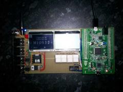
...after seeing a few prototypes of other stm32f4-core-boards i decided to upload a few photos from my board. it uses 2 dogm-glcd-displays, 2 midi-ports, 4 j10-buttons and the sd-card-connector... heres the top-view without any modules: and here the bottom-view: cheers, mOnO
-
-
This conflict only exists for the MIDIbox CV V2 application which accesses the AOUT module from an interrupt service routine, and not from a task where Mutex based synchronisation would be possible. If the application would access the AINSER module as well, it would need to do this from the ISR, and this dramatically reduces the CV update rate. I guess that everybody prefers high update rates instead of the possibility to connect analog inputs to an AINSER module. The good news are, that the analog inputs of STM32F4 are more stable than the ones of STM32F1 and LPC17. Again +1 for using a MBHP_CORE_STM32F4 module! Best Regards, Thorsten.
-
The AINSER8 or 64 board will neither be supported by LPC17, nor STM32F4 since it conflicts with the AOUT module at J19 which will be accessed by a fast timer interrupt. Therefore: LPC17: up to 6 analog inputs at J5A and B (J5B.A6 and A7 are used for MIDI3) STM32F4: up to 8 analog inputs at J5A and B Best Regards, Thorsten.
-
STM32F4 is typically ca. 50% faster than a LPC17 core. Also the DMA implementation is better (no shared interrupt for all channels) which results into faster SRIO and SD Card accesses. Best Regards, Thorsten.
-
Nice that you find the error! :) Here a preliminary version which provides more event pool memory for the STM32F4: http://www.ucapps.de/mios32/midibox_ng_v1_030_pre1.zip Best Regards, Thorsten.
-
TK definitely didn't give up. I have a prototype MBHP-STM32F4 board here so it's in the testing phase
-
Dear Thorsten! Do not give up! We are waiting MBHP based STM32F4 Discovery, with great interest. Homebrew from Russia.
-
At this point, the only possibilities are: 1. Dead CLCD - time to test another CLCD? 2. Something weird with the software and/or configuration - das Heisst: keine Ahnung... TK! Wo bist du denn? :P 3. Bad wiring between the STM32F4, the 74HC595 and the CLCD. Did you try another 74HC595? - time to post a picture of your wiring (both sides, high-res please)
-
Also, I just compiled the MIDIbox NG application for the STM32F4 on my pc using the latest SVN source. You can try it out: http://sneak-thief.com/MIDIboxNG/project.hex It loads fine and gives me the appropriate message for my setup: [387180.219] [MBNG_LCD] no response from CLCD #1.1 [387180.220] [MBNG_LCD] no response from CLCD #2.1
-
OK, open MIOS, clear your terminal screen and send load the Bootloader 1.015 hex file - not the MIDIbox NG application. -> What does the terminal say at the very top? For exmaple, my STM32F4 core isn't hooked to and LCD or anything else and it says: [386343.822] Initialize LCD #1 [386343.886] Failed - no response from LCD #1.1 [386343.886] Initialize LCD #2 [386343.950] Failed - no response from LCD #2.1
-
WOW! GREAT WORK! I am using the new STM32F4 core and immediately noticed that executing of big NGR scripts is much faster! TK, did you modify the SD card access? Or is it because the new core? Best regards Marxon
-
Did you compile for the new target? Edit: ok, I just saw that you can now download a binary version for STM32F4, and you skip compiling yourself. So, you are using that one?
-
For anyone who's interested in having the MIDIbox CV 2 do any CV-input processing, there are a few things to consider... The processing rate will likely be in the 1-2KHz range. Not really great for audio but perfectly acceptable for a wide range of other kinds of control-voltage signals, eg. note quantizing. The quantizing hasn't been added yet but it's in the to-do list. If you're using the LPC17 core and the AINSER8/AINSER64 board, you'll need to limit the input voltage to 5V. I recommend putting a 100KB pot or trimmer in front of the circuit linked below. The CCW pin should be connected to ground, the CW pin to the voltage input and the middle pin goes to the 10K Ohm resistor on this circuit: http://www.eevblog.com/forum/projects/pic-input-protection-using-a-zener-diode/msg21840/?PHPSESSID=33bbdf2e2a88957db87cce882680f1ca#msg21840 To calibrate it as a 2:1 voltage divider, send the 100KB pot/trimmer a 10V signal and adjust it until the output is 5V. (corrected - the LPC17 board can't use the AINSER board either) *** PLEASE NOTE: you'll need to limit the input voltage to 3.3V *** To do so, you'll need to build this circuit which limits the input to about -0.2V to 3.3V, regardless of the input (within reason, of course) That means you can send the analog inputs -10 to +10V and it will scale that voltage by 1/3, reject all negative voltages. Therefore, 0-10V will give a result of 0 to 3.3V. Circuit description: 1. I recommend putting a 100KB pot or trimmer in front of the circuit linked below. The CCW pin should be connected to ground, the CW pin to the voltage input and the middle pin goes to the 10K Ohm resistor on this circuit: http://www.eevblog.com/forum/projects/pic-input-protection-using-a-zener-diode/msg21840/?PHPSESSID=33bbdf2e2a88957db87cce882680f1ca#msg21840 *** Instead of connecting 5V to the diodes, used 3.3V *** 2. To calibrate it as a 3:1 voltage divider, send the 100KB pot/trimmer a 10V signal and adjust it until the output is 3.3V. 3. Analog Core inputs: - If you're using the STM32F4 core, you can use up to 8 ADC inputs on the board itself (J5A & J5B). - If you're using the LPC17 core, you can use up to 6 ADC inputs on the board itself (at J5A and B but NOT J5B.A6 and A7 as they're used for MIDI3).
-
V1.015 is available under http://www.ucapps.de/mios32_download.html workaround for USB MIDI under Windows when more than 1 USB MIDI port is enabled various LCD/GLCD driver updates for STM32F4 Best Regards, Thorsten.
-
Thanks a lot! That's interesting... I'm in the process of starting a project, and gathering some details. In case I'll start with the STM32F4 I'd be very glad if you could share the preliminary version. By the way, may I also ask what's the scan rate Midibox KB achieves? I'll let you know, Philip
-
Prototype STM32F4 MIDIbox boards and LRE8x2 boards received! Time for my Reichelt order so I can start stuffing these boards:
-
Very frustrating, I decided to go with the LPC17 version since it looked like a quicker path to a completed project. In hindsight, I wish I went the STM32F4 route...
-
The only missing piece is an EEPROM emulation for STM32F4. I will implement this sooner or later, but it won't be available in the next 2..3 weeks. If it's ok for you to start with a MBKB which can't store the parameters, I could give you a preliminary version. Best Regards, Thorsten.
-
Hi everyone, I wanted to ask if there are any plans to bring the Midibox KB application to STM32F4, since I have a spare board and I would like to do something with it... Thanks, Philip
-
New topic: How about skipping ethernet altogether and going directly to WiFi? Adafruit offer a cheap breakout module running over SPI: http://www.adafruit.com/products/1469 Is there a free SPI buss for this purpose? I notice the STM32F4 board does not yet have an ethernet connector.
-
The STM32F4 version of the MIDIbox CV 2 uploaded successfully and MIOS is happy: Operating System: MIOS32 Board: MBHP_CORE_STM32F4 Core Family: STM32F4xx Chip ID: 0x10016413 Serial: #32002C000147333139303639 Flash Memory Size: 1048576 bytes RAM Size: 196608 bytes MIDIboxCV V2.000 © 2014 T.Klose Also, for the MIOS32 toolchain ( http://www.midibox.org/dokuwiki/doku.php?id=windows_mios32_toolchain_core ), I modified the ENV variables to correspond to the STM32F4: set MIOS32_GCC_PREFIX=arm-none-eabi set MIOS32_FAMILY=STM32F4xx set MIOS32_PROCESSOR=STM32F407VG set MIOS32_BOARD=MBHP_CORE_STM32F4 set MIOS32_LCD=universal Should I post this update here? http://midibox.org/forums/forum/13-midibox-documentation-project/