Leaderboard


Popular Content
Showing content with the highest reputation on 11/24/2015 in all areas
-
got them. tanks a lot1 point
-
got it thx1 point
-
Hi Martin, I have just got mine knobs. Thanks a lot.1 point
-
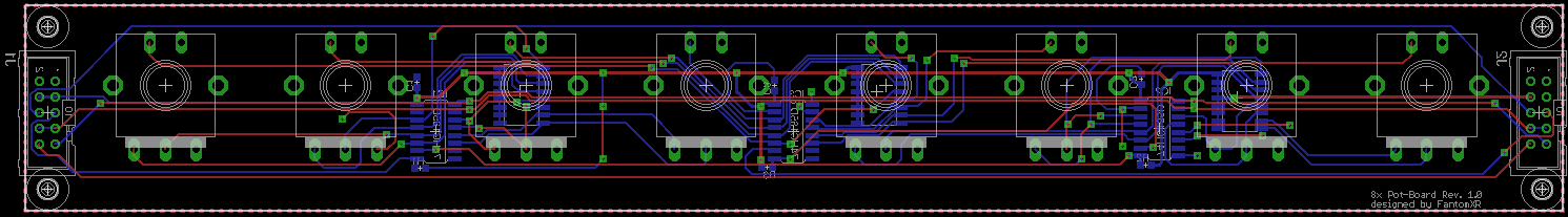
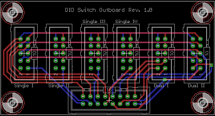
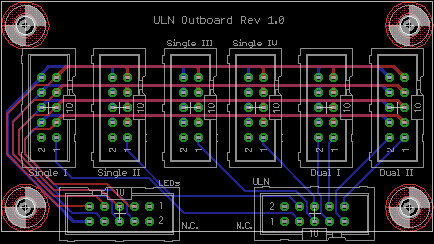
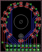
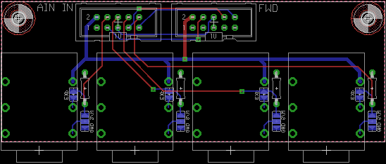
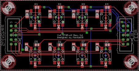
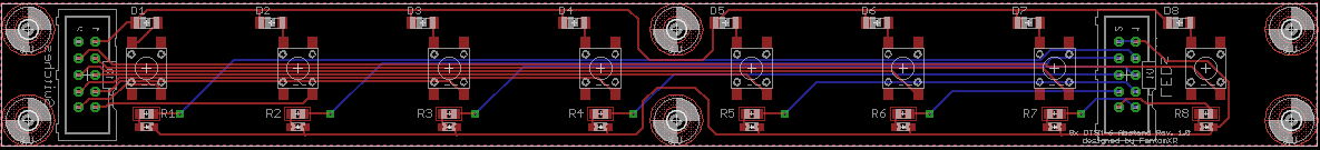
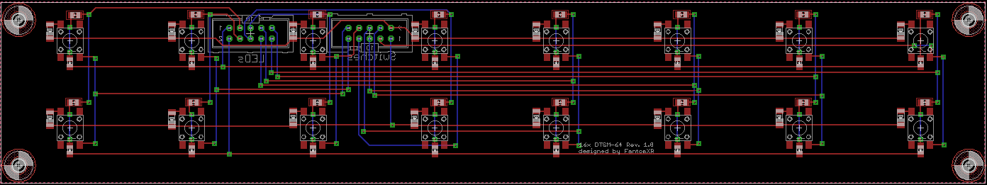
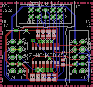
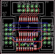
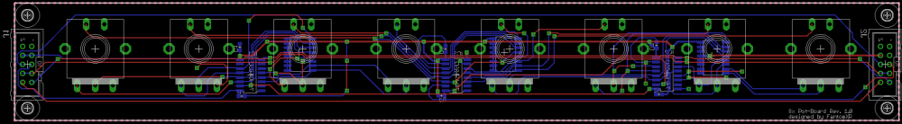
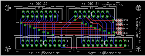
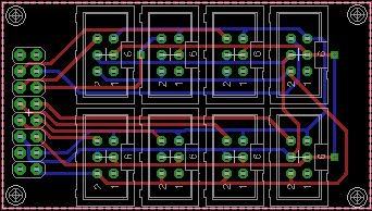
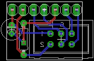
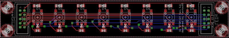
Hey people, as I'm an active member of this community for quite a long time and I really appreciate the help that one gets here, I'd like to share the PCBs with you, that I've created over the last two years. I already created a wiki-entry a while ago but I think this might be overlooked and maybe I can give you some inspirations with those PCBs. The layouts are tested but there might be a few mistakes on the silkscreens. If you found out, somethings wrong, please do not hesitate to contact me. Also I didn't take time to make a clean schematic.... so this might look sometimes confusing ;-) But as I said: It's all tested and should work. I will not share the PCBs I recreated from TKs schematics, because you can get the PCBs either at SmashTVs shop or the *.brd-layout on ucapps and I don't want to compete with Tim. So let's start. If there is something in the layout that needs to be explained, I will add a little description to them. In general regarding the SMD-layouts: They can be soldered by hand with a good solder iron. There is no need to have an reflow oven or similar. 1x DIN (SMD): Description: No mounting holes due to a small size! 1xDIN.zip 1x DOUT (SMD):Description: The package, that is labled with ULN2803 can be either used for of course an ULN. But the footprint fits also resistor-array (f.e. bourns 4816-series). No mounting holes due to a small size! 1xDOUT.zip 8x Encboard (SMD):Description: This is an pcb that can be directly equipped with ICs and than be attached to the core without any other DIN modules. Distance between encoders: 29mm (fits the DTSM-64 distance layout (see below)). 8xEncboard.zip Fatar Adapter:Description: This adapter can be used to connect an 76 or 88 keybed to a DIO-module. You need to solder the jumpers as needed. Fataradapter.zip DIO-Breakout:Description: This adapter is used to split the pins of an DIO-module into more usable pin-headers. See my switch-boards below. DIO-Breakout.zip ULN Breakout:Description: Same as DIO-Breakout. ULN Breakout.zip LED Ring (SMD):Description: This LED ring is made for 0805 LEDs. Good soldering skills needed. LEDRing.zip Neutrik-jack PCB:Description: This PCB can be used to attach easily sustain- or expressionpedals to an AINSER8 module. Solder jumpers as needed and don't forget the 1k pull up resistor when using it for sustain-pedals / switches. Neutrik.zip OLED Breakout:Description: The module can be directly connected to J15A/J15B of the core. You can then connect OLEDs in conjunction with the display-board directly to the core without soldering any wires. OLED Breakout.zip OLED Displayboard:Description: You need this pcb in conjunction with the OLED Breakout above. This pcb will be soldered directly onto an OLED which you can get for good prices on ebay or aliexpress. Pay attention, that this will only work for OLEDs which have 7 pins single-header connectors. OLED Displayboard.zip 2x4 DTSM-64 (SMD):Description: You can connect this PCB directly to the DIO- / ULN-Breakout board (see above), but it should work with classic DIN/DOUT modules too. Switches are DTSM-64. 2x4DTSM.zip 8xDTSM-64 (SMD):Description: You can connect this PCB directly to the DIO- / ULN-Breakout board (see above), but it should work with classic DIN/DOUT modules too. Switches are DTSM-64. 8xDTSM64.zip 8xDTSM-64 distance (SMD):Description: Distance between the switches: 29mm. You can connect this PCB directly to the DIO- / ULN-Breakout board (see above), but it should work with classic DIN/DOUT modules too. Switches are DTSM-64. 8xDTSM_distance.zip 16xDTSM-64 (SMD):Description: You can connect this PCB directly to the DIO- / ULN-Breakout board (see above). Won't work with classic DIN/DOUT modules. Switches are DTSM-64. Distance: 29mm. 16xDTSM.zip That's it for now. This list will be updated if there are any news.


 1 point