

workspace
-
Posts
42 -
Joined
-
Last visited
-
Days Won
1
Recent Profile Visitors
5,906 profile views


workspace's Achievements
MIDIbox Newbie (1/4)
5
Reputation
-
Troubleshooting Wilba hardware or SEQv4+ software bug
workspace replied to workspace's topic in MIDIbox SEQ
Dear Andy Thanks for checking on your side. I bought two replacement 74HC595 today and everything is back to normal But indeed, those Matias switches look very nice! Maybe I will pimp my SEQv4 at some day. In the meantime it is mainly the "brain" because I control most of it with one of your wonderful 1st gen BLMs! But then the 2nd gen is quite tempting... the only thing I miss are more OUTs (4xI2Cs) to run it standalone. Any thoughts in this direction? Greetings Michael -
After using my SEQv4 for several years, I have encountered a strange bug that may be hardware or software related. When I select track button 3 or 4 in edit mode and activate step 1 and 2 (GP1 + GP2), these buttons and the step view button are freezed and can't be changed anymore unless I select a different mode or track. Since I think I am the first to have this problem, I suspect it is a hardware error. All these buttons are connected to DOUT3 of shift register U7. But swapping this IC with the other 74HC595 didn't help. Is this still a software bug? It would help if somebody with a wilba panel could confirm or deny this strange behavior. DOUT3 is the only SR of the shift register, that has 2 free pins. Maybe this is a problem? Thanks and a happy new sequencing year to everybody! Michael
-
The two sides of R1 have +4.98V and +12.00V so I guess the LM4040 is bad as well. Thanks for you support!
-
I really don't know how this happened, I managed to miss-orientate all of the opamps! At least a learned now how to desolder smd parts with hot air.... After resoldering them in the correct way, the module shows the two top led in red, the 3rd in green the 4th dim red and 5-8 green again. In the CV configuration page 1st led reacts to cv1, 2nd to cv2, and 4th led to cv3. all the other leds show no sign. Is it possible that i burnt the opamps? I used the hot air (300 C) for about 1-2 seconds on each opamp. lgm-
-
The cable is ok. I get the +12 / -12. Layout would be great. Thanks Michael
-
Hi everybody I have problems with my eurorack expander a1 cv module. It seems that I have a short somewhere on the transmute8 board. The tiptop uzeus (eurorack power supply) is blinking, which tells you that the module is shortening the power. This also happens if I connect the transmute8 without superdac and octal boards. I already checked for solderbridges and orientation of the powerplug. Is there a schematic of the board I can use to find the short? and whats the best approach to find it? Best Michael PS: I attached the cv module directly to J19 of my core module. this should work, right?
-
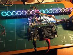
OLRE16 with Lattice CPLD as Clocking/Addressing interface
workspace commented on Antichambre's gallery image in Members Gallery
 magnificent!
 -
very nice!
-
no. but it's still on my todo list. i'll post the command line if i work out. michael
-
Dear Peter, thanks for your reply. I'm thinking about another approach with groups, patterns and tracks that has more flexibility and could solve this. But I worrying that it also would lead to a MBSEQ V5 .... Best Michael
-
In my setup I used to assign MIDI ports OUT1-4 (and channels) to all the tracks I needed. I saved several patterns / groups with this settings. Recently I changed my hardware setup to Quad IIC. Unfortunately all my patterns are saved with OUT1-4 ports. Is there a way to change this without editing every track and saving the pattern again? I might also want to change my setup temporarily to use the USB ports for this patterns and experimenting with the sounds of the softsynths on my computer. I reckon there is a best practice to do this. Maybe sending CC using a loopback track to set/change the MIDI ports? But before I dig deeper into this I wanted to know if I'm on the right track or if there is an easier / more elegant way. Thanks Michael
-
programming under windows with the gui version worked perfectly. now everything is running. if i find the time i will investigate into the command line options for pk2cmd. i think programming should also possible with this software. thanks everybody for the support.
-
i checked pin 6. the firmware is not running. when i read the memory of the pic i get just get FF00s. i also tried programming with different voltages. same result. so i guess programming is not that straight forward with the pk2cmd software. i have the diamex programmer. i think i have to install windows for the gui version...
-
I used the IIC_MIDI Test V1.002 application. the scan command lists for IIC1-4"not available". I haven't soldered the red (status?) LEDs yet.
-
I use SmashTVs quad_iic board, the 10uF cap are there, but not green LED. For now I think the problem is the pk2cmd software. I'll have to install a virtualbox for the gui / windows version.
