smokestacksproductions
-
Posts
95 -
Joined
-
Last visited
-
Days Won
1
Content Type
Profiles
Forums
Blogs
Gallery
Everything posted by smokestacksproductions
-
Open it up and post a picture of the pcb inside (top and bottom) - then we can help you figure it out
-
LPC17 & CORE32 Expansion Board for Seq V4
smokestacksproductions replied to smokestacksproductions's topic in MIDIbox SEQ
Here is the corrected .brd file. If someone can look at it and tell me if you can spot any other errors, I will render the positives and etc. quick view: .brd: AOUT + MIDI IN-OUT 3-4 v1.1.rar Thanks!
-
LPC17 & CORE32 Expansion Board for Seq V4
smokestacksproductions replied to smokestacksproductions's topic in MIDIbox SEQ
This explains why my prototype did not work! I will correct this in the .brd and re-upload. -
SEQ V4 TPD Track Position Display (+ live goa trance)
smokestacksproductions replied to Hawkeye's topic in MIDIbox SEQ
Didn't you post schem of this somewhere? ok, I found this: MIDIbox SEQ V4 BPM Dig by TK, but I thought you made a schem of how your TPD was connected, edit: nevermind, it's just a matrix with the sr pins defined in the hardware file, right? -
Smash, Thanks for stocking the Seq CS PCB's. They are really beautiful. Stuffing the board was an absolute breeze. It is just so nice to work on boards like this compared to home etched... The price you charge for the board is very generous too, Absolutely top notch stuff!
-
I would also like to make a PCB with step, tempo, and TPD displays, I'm feeling kind of torn between integrating the shift registers or just using one of smash's doutx4 because they are so much nicer than anything I could etch at home. Hawkeye: Can we please haz diagram? ... Just kidding, I will try to lay it out based on the information you've already posted in the past, I might have some questions. Thanks for pushing for these awesome features!
-
LPC17 & CORE32 Expansion Board for Seq V4
smokestacksproductions replied to smokestacksproductions's topic in MIDIbox SEQ
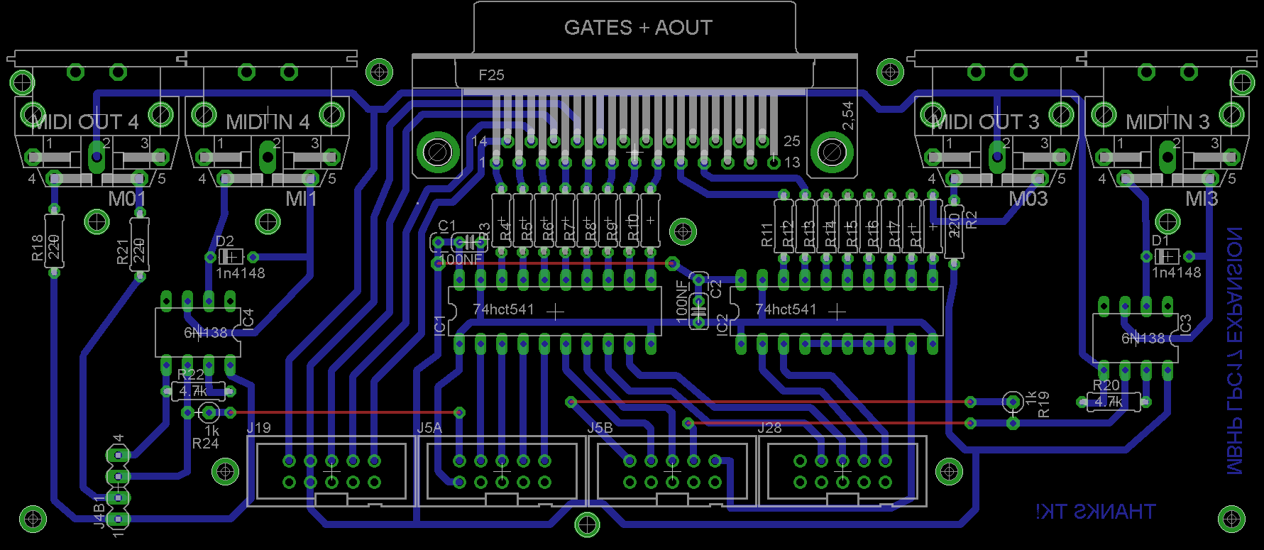
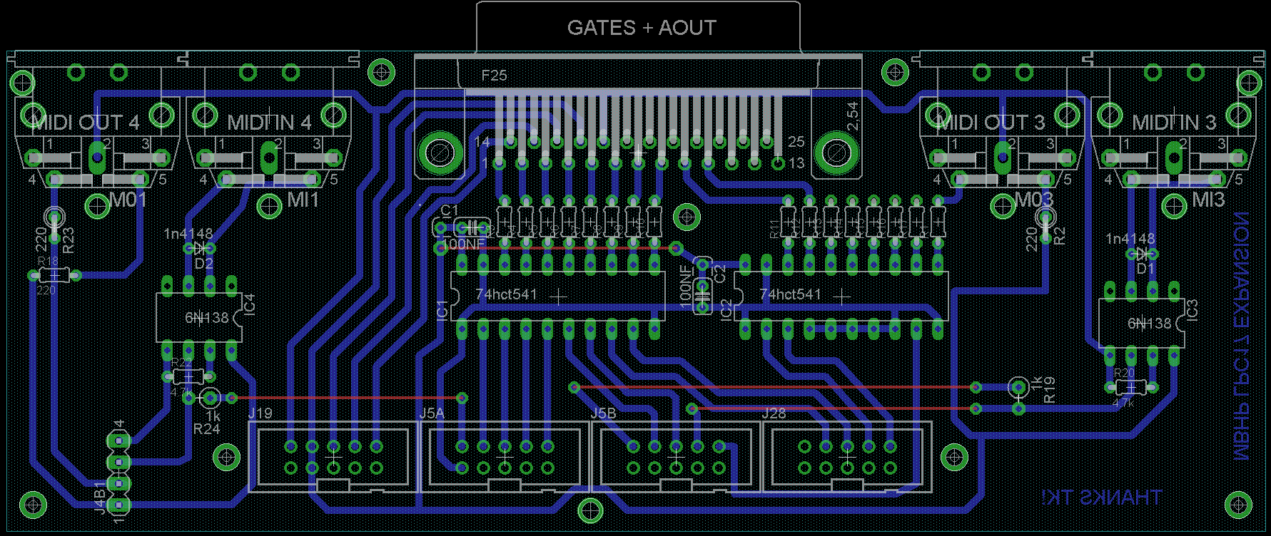
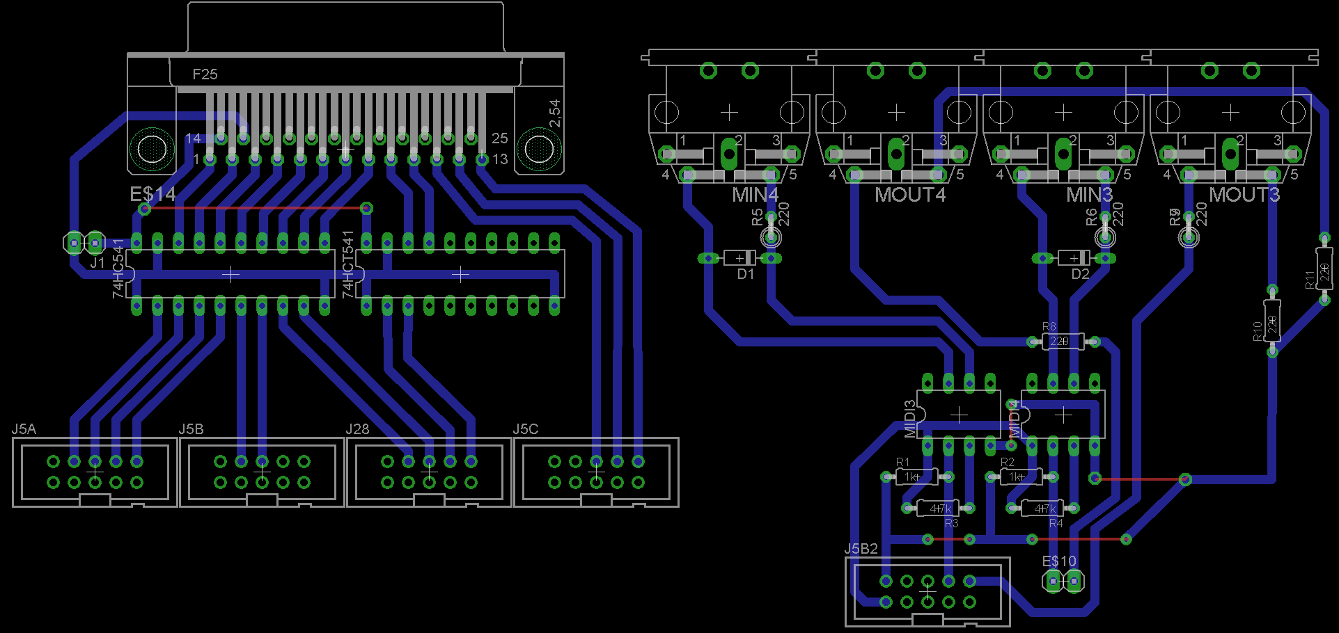
OK! I have added MIDI I/O 4, here is the quick view of the new layout: Below you will find a .rar archive which contains: 1. .brd file (you may open and modify with eagle) 2. full color quick view to assist in assembly 3. negative monochrome render of bottom traces, pads, and vias (for negative photo resist process) 4. positive monochrome render of bottom traces, pads, and vias (for positive photo resist process) #4 has been optimized in photoshop to use less etchant (this is the one I will be using) I will be receiving the components for this board today. I'll let you know how it all works out after this weekend. In the meantime, if someone spots an error, or has some suggestions to make, please let me know! Here are the files: seq expansion.rar
-
LPC17 & CORE32 Expansion Board for Seq V4
smokestacksproductions replied to smokestacksproductions's topic in MIDIbox SEQ
OK, I will add the additional midi ports! -
LPC17 & CORE32 Expansion Board for Seq V4
smokestacksproductions replied to smokestacksproductions's topic in MIDIbox SEQ
That's great! I just ordered the components for it yesterday. I'm going to etch the pcb and assemble it over the weekend, I'll let you know how it works out on monday. In the meantime, I'm open to suggestions for how I could improve this board. Do you think it is wise to add two more ports for midi i/o 4 ? or should I just add a single port for the blm connector? I could also add midi thru ports, but they may be redundant if the MBseq has a "soft" midi thru function (I just got my seq up and running last week, so I still have a lot to learn about this amazing software. -
LPC17 & CORE32 Expansion Board for Seq V4
smokestacksproductions replied to smokestacksproductions's topic in MIDIbox SEQ
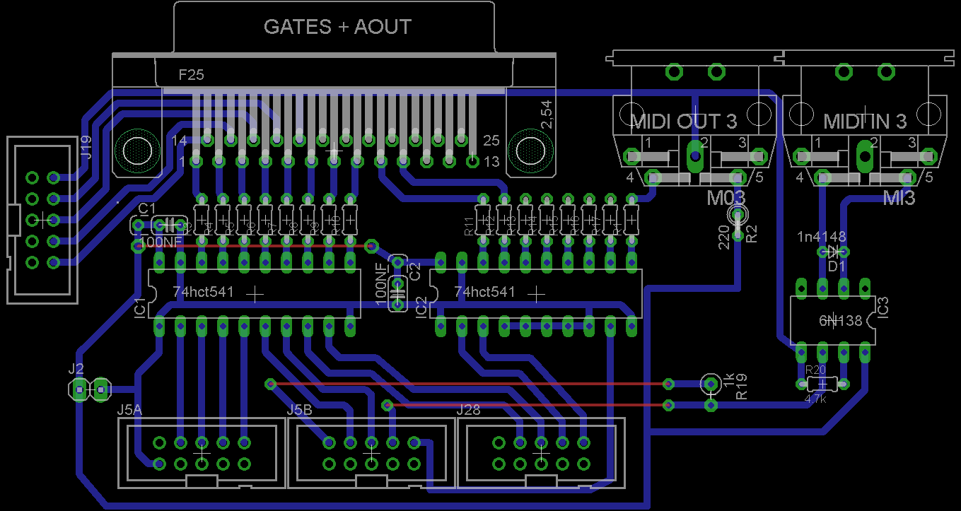
I have revised the PCB according to an updated schematic TK provided. This latest version is a bit simplified, I have eliminated MIDI I/O 4 (reserving this for the BLM connector down the road) and I have buffered the Midi 3 output to 5v with one of the free pins on the level shifting IC. See the attached .brd and quick view .brd: AOUT + MIDI IN-OUT 3.rar .png quick view:
-
Lasercut Acrylic Case+ Frontpanel for SEQv4
smokestacksproductions replied to smokestacksproductions's topic in MIDIbox SEQ
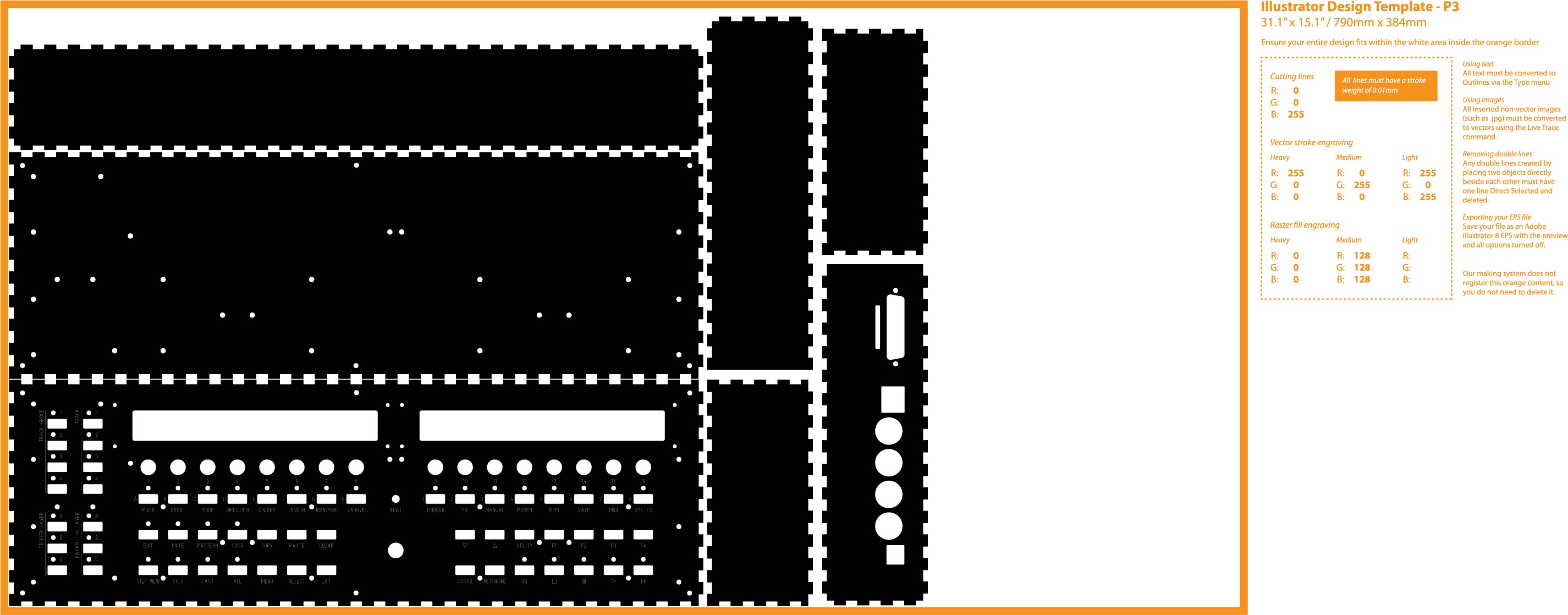
1. Open the .fpd file in frontpanel designer (the free app from frontpanel express) 2. Export as .svg 3. Open .svg in illustrator or other vector art software 4. Paste on to Ponoko Template 5. Change line color to correspond with desired cutting/engraving setting, modify dimensions and etc. That's all there is to it. BTW, I used a free web-based app call Box Maker to generate the interlocking edges of the enclosure: http://boxmaker.rahulbotics.com/ - you enter your desired dimensions and it generates the six sides for you. - You can even specify the amount of material that is vaporized by the laser when cutting, and the software will automatically compensate for this to make sure all your joints are very snug. It's really important to use this feature if the enclosure will be held together by friction and standoffs (as opposed to the t-nut cutouts on a Shruthi Case) -
Hello, I have converted wilba's seqv3/v4 frontpanel layout for laser cut acrylic. I have also added interlocking sides and bottom to make a sammich-style enclosure. It is all laid out on a P3 sized template for ordering from ponoko. This template is designed for 3mm laser-cut acrylic and the cost for standard colors (making and material included) is less than $50.00! It's about $10.00 more for matte finish (which is what I have ordered) I have attached the necessary files in case they may be helpful to someone else who wants a low-cost enclosure/panel for their MBseq. *Note - (you should alter the rear panel cutouts to match your core, and expansions) Later I will post a diagram and a list of the spacers required to assemble this enclosure. With the right hardware, I believe this case will be quite sturdy (considering the size of the entire unit and the fact that it is cut from acrylic and not aluminum) I will post pictures and feedback once I have assembled the case. The ponoko site says their current turnaround for laser cut orders is approx. 2 weeks, so I'll update this post when my order arrives. .eps for illustrator and .svg for freeware vector art programs are both contained in this .rar archive, you can download these and modify them, the .jpg attached to this post is simply for visualization purposes, while the vector files in the .rar archive are formatted with the proper colors for cutouts and engraving (ponoko) Enjoy! Quick View: and the vector files: enclosure.rar
-
Hello, I have made a PCB that breaks out all the I/O for 5v buffered gate triggers and additional midi ports that are found on LPC17 and CORE32 for MBSeqv4. The goal is to break out all the connections using 2x5pin IDC Headers that will connect 1:1 with the corresponding headers on the core module. The attached files are for LPC17 (which I am currently using) and they can be easily modified for core32 (swap midi I/O pins, etc.) I have integrated 5v level shifters for the 8 gates and clock start/stop etc. I have also integrated the necessary hardware for Midi I/O ports 3,and 4 (optos, resistors, etc.) I would like to make these additional midi ports operate at 5v (instead of 3.3v) to ensure compatibility with older midi devices. I'm not sure what changes are necessary to do this. As you can see there are quite a few pins free on the 74hct541 if those are required, I was wondering if I supply the "m+" pins (on the midi out ports) with 5v instead of 3.3v will this achieve the same result? If so, should the 220ohm resistor be changed to a different value? Please have a look at the eagle and quick view files I have attached. Your input is greatly appreciated! quick view .png: eagle .brd: seq expansion.rar edit: TK has provided an updated schematic of the buffered gates and midi outputs, so I will revise my PCB accordingly and repost.

-
My SEQV4 - Finished electronics !!!
smokestacksproductions replied to Lamouette's topic in MIDIbox SEQ
This could be risky, sometimes there are caps and current limiting resistors (on the LCD PCB) before the A and K, and you would be cutting them out of the circuit. -
MB SEQ and ROLAND MC-909
smokestacksproductions replied to smokestacksproductions's topic in MIDIbox SEQ
This totally makes sense! Instead of cutting traces on my lpc17 to route to the level shifter, can I just install a IIC midi module and supply it with 5v? -
MB SEQ and ROLAND MC-909
smokestacksproductions replied to smokestacksproductions's topic in MIDIbox SEQ
It gets more interesting! - If I pass thru another synth or midi device that has a soft thru (where midi in is routed to midi out via internal processing, for lack of a physical midi thru jack) then is works perfectly. The MC-909 responds as usual. So why doesn't it work when connected directly? Could it be a faulty optocoupler? Or perhaps MBSEQ is spitting out some data that the MC-909 doesn't like, which gets filtered out by an intermediary midi device? What do you guys think? It's nice that I've found a workaround, but it's going to bother me until I figure this out! -
Hello, I am unable to use my Roland MC -909 with the Midibox seq I just built. Here is a summary of the testing I have done: 1. Connect lpc-17 midi out 1 to MC-909 midi in. Set the appropriate ports and channels on the MB-SEQ to route a track to the midi output. - MC-909 does not respond to notes, CC#, clock, NOTHING! I have also tried live play and triggering from an external controller, and I can see the notes coming in and out with the MBSEQ midi monitor, but nothing happens on the MC-909. 2. Connect ext. midi keyboard directly to 909 to make sure it's working - everything behaves as expected. Notes trigger, CC#s register, etc. - this tells me that settings on the keyboard, and the 909 are correct. - now I think the problems is with the output of the MB-SEQ 3. Connect the MB-SEQ to my computer via midi interface. When I look at the incoming messages in midi-ox, notes and CC#s are transmitted as expected. Ext. keyboard is able to pass through the MBSEQ and play VST's and etc... This leaves me stumped. I thought maybe it was an issue with using USB to power the MBSEQ, so I hooked up a 7.5v 1-amp power supply and although my LCD backlights are a little brighter, The MBSEQ still won't trigger the MC-909 Can anyone suggest another test or idea? The midi settings in MC-909 are very limited and simple. I don't think it's an issue on the 909 anyways since it works fine when I take the MBSEQ out of the equation. Thanks for your help!
-
Hello, I am trying to get my homemade Aout LC to work with LPC17 running seq v4. Which diagram is correct for this setup? I have seen: 1.CORE8 to AOUT (seqv3) 2.CORE8 to AOUT LC (Midibox Sid) 3.CORE8 to AOUT LC (Midibox CV) I have also seen the Seq V4 interconnections diagram for STM32, but this shows connection to a parallel port with labels that are not consistent with the other diagrams. can someone please tell me the correct pinning to connect AOUT LC to LPC 17 ? Also, I remember a thread TK wrote a while back about his AOUT breakout box with level shifters, but I can't find that either. Thanks! OK, I figured it out. Connection from LPC17 to AOUT LC is 1:1 - it's so simple, I didn't think it was possible!
-
Buying: mb6582 front&back panels for PT-10
smokestacksproductions replied to FLD's topic in Fleamarket
you can open wilba's layout in frontpanel designer (available free on the fpe website) and export it as a .svg file. You can then paste the contents of the .svg onto the ponoko templates available on their website.