

endernoumea
-
Posts
56 -
Joined
-
Last visited


endernoumea's Achievements
MIDIbox Newbie (1/4)
0
Reputation
-
Hello, I have two questions about this command : 1 - Is it possible to precise the type of hw_id in the meta command SetBankOfHwId ? I need it to change some encoders bank but my Dout matrix is receiving the instruction as well (which is not needed) In example something like : meta=SetBankOfHwId:ENC:14 .. to change only the bank of the encoder 14 ..or.. meta=SetBankOfHwId:ENC:any .. to change the bank of all the encoder and nothing else 2 - Second question, is it possible to change the bank of an item defined by a matrix ? If i use... meta=SetBankOfHwId:1001 ...to change the bank of my RGB matrix led event i have an error in MIOS studio like : ERROR: expecting 1 values for meta type in EVENT_BUTTON ... meta=SetBankOfHwId In other words: Is it possible to have a new instruction called SetBankfwd_id where we can use the same events like fwd_id ? :p
-
I did what we supposed at the end : 1 - I setup the RGB matrix with driver connected to 5V permanentely. (so i only need 3 SR per matrix) i declare it like this : DOUT_MATRIX n= 2 rows=4 inverted_sel=1 inverted_row=1 sr_dout_sel1= 0 sr_dout_r1= 5 sr_dout_g1= 6 sr_dout_b1= 7 led_emu_id_offset=1501 DOUT_MATRIX n= 3 rows=4 inverted_sel=1 inverted_row=1 sr_dout_sel1= 0 sr_dout_r1= 8 sr_dout_g1= 9 sr_dout_b1= 10 led_emu_id_offset=1801 note : the sr_dout_sel=0 (i think this is the dummy SR because i read it in many settings) so for 2 RGB matrix i only need 6 SR. (5 to 10 in my case here.) The Blackscreen are now as brighter as they can and i can control them with the rgb=r:g:b command. Of course this means that my RGB matrix are only 1 row maximum.
-
I setup 3 radio buttons that represente 3 functions i can assign to my encoders. The objective is to change to color of the screen according these 3 buttons when i move an encoder. here is how i do that : EVENT_BUTTON id= 35 type=CC chn=1 cc=16 button_mode=OnOnly range= 0:0 radio_group=1 EVENT_BUTTON id= 39 type=CC chn=1 cc=16 button_mode=OnOnly range= 1:1 radio_group=1 EVENT_BUTTON id= 40 type=CC chn=1 cc=16 button_mode=OnOnly range= 2:2 radio_group=1 DOUT_MATRIX n= 2 rows=4 inverted_sel=1 inverted_row=1 sr_dout_sel1= 0 sr_dout_r1= 5 sr_dout_g1= 6 sr_dout_b1= 7 led_emu_id_offset=1501 EVENT_ENC id= 1 hw_id=1 bank= 1 fwd_id=LED_MATRIX:1 fwd_to_lcd=1 type=CC chn= 1 cc= 16 range= 0:127 offset= 0 ports=1000100000001000 lcd_pos=1:1:1 label="ENC #%3i %3d@(1:16:1)%B" EVENT_ENC id= 1001 hw_id=1 bank= 1 if_equal=Button:40:2 fwd_id=LED:100 EVENT_ENC id= 1002 hw_id=1 bank= 1 if_equal=Button:39:1 fwd_id=LED:102 EVENT_ENC id= 1003 hw_id=1 bank= 1 if_equal=Button:35:0 fwd_id=LED:101 EVENT_LED id=100 fwd_id=LED:1502 rgb=15:0:0 EVENT_LED id=101 fwd_id=LED:1502 rgb=0:0:15 EVENT_LED id=102 fwd_id=LED:1502 rgb=0:15:0 My problem here is that the led are activated only when the encoder value is > 63. I want it to be activated everytime i move the encoder. Can i force it ?
-
It's working :)
-
I think this is the answer. It might be ok for a led but it's not enought for a LCD blackscreen. (at least not those like mines) I was wondering something but I don't know if this can works: 1- Setup 3 differents dout matrix to separate my 3 rows on 3 differente boards. 2- the replace the driver by a constant 5V This should allow me to use the rgb=r:g:b instruction from the matrix function and avoid the scanning effect right ? (I have spare dout I could use for that)
-
No I have no OSC sorry :/ Is there any way to drive RGB led without matrix ? because it seems that it's not allowed to use rows=1 in the matrix definition.
-
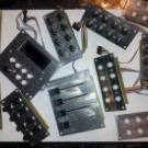
The picture is from the original post of the protodeck project : http://julienbayle.net/works/creation/protodeck-midi-controller-for-ableton-live/ I use it as a model to describe what I am using here. I have 2 differences : - I use no resistance nor resistor array. - I will have 22 RGB at the end, so 3x8 (not 8x8) I just setup what you said on a breadboard and the led still not bright. I cannot test the rows=1 because it generate an error in mios : [839542.973] [MBNG_FILE_C:10] ERROR invalid row number for DOUT_MATRIX n=1 ... rows=1 (only 4 or n*8 allowed)
-
I actually setup only 16 screens but I will have 22 of them at the end so the 1 row matrix cannot fits my requirements. The LCD are common anode. The data sheet can be found here : http://www.ebay.com/itm/16x2-Character-LCD-5V-RGB-Backlight-Negative-Mode-RGB-on-Black-2x16-Row-USA-/150826420761 So i declare my matrix like this : DOUT_MATRIX n=1 rows=4 inverted_sel=1 inverted_row=1 sr_dout_sel1=1 sr_dout_r1=2 sr_dout_g1=3 sr_dout_b1=4 led_emu_id_offset=1001 The wiring is inspired from the "hacked dout" of the protodeck project but without any resistance nor resistance array.
-
yes exactly. On the picture they are ok but it was before i use the dout matrix. They were connected directly to 5V at this time to "test" the colors. The RGB matrix is working very well. I can change the color using the rgb=rr:gg:bb in my led event but it's definatlly not bright enought to be workable by day.
-
I just setup the dout Matrix to control the RGB screens. I take some time to understand how it works but now it's ok and it's amazing to watch all the colors available. I'm now facing a new issue. I think it's related to the "non-permanent" current going thru the matrix. I mean that my LCD are not glowing as expected. (on the picture the LCD glowing OK but they are directly connected to a power source and not to the matrix) I remove all the resistor from the dout and it's kinda better but not enought. I tried two circuits, on with ULN 2803 and one with 74HC541 which improve the result but not enought again. I'm am now wondering if I can use a capacitor to smooth the current drop but I'm not sure on the way to do it. If this kind of trick cannot works i guess I will have to use DOUT module without matrix but this will make the RGB control much more complicated. Any advises ? Thank you in advance, Ender
-
Tada !!!! Everyhting works ! Finally :)
-
Hi ! I had 2 crazy months at my job so I did not answer before... sorry about that. All the LCD are now working perfectly without using the above circuit. I just split the LCDs in 2 chains and plug half of them on J15a and the other half on J15b. It means 8 lcd screens per socket in my actual case (16 in total). In the final configuration i should have 22 LCD screens so I will keep in touch about this workaround. Regards, Ender
-
 Yes please those files are welcome. I have finally found a front panel really cool and affordable :) Thank you !
 -
Hi ! I received the 74HC541 and make the circuit as illustrated before. I also added a 220r for D0 to D7 and powered the Dout with 5V from J4A. Actually none of this works but i believe i miss something with : "BL and V0 are replicated for every 4 to 8 LCD units. " because i didnt do anything about that... what does this comments means please ? Ender