mono
-
Posts
104 -
Joined
-
Last visited
-
Days Won
2
Content Type
Profiles
Forums
Blogs
Gallery
Everything posted by mono
-
-
-
-
hallo xii, habe gerade deinen beitrag gelesen und denke ich habe da was für dich! unter diesem link: http://www.chipkit.net/forum/viewtopic.php?f=15&t=2561 findest du eine "kleine" beschreibung meines projekts. natürlich ist der beitrag schon etwas älter. bin im november vom pic32 (fubarinosd) auf midibox (lpc1769) umgestiegen und arbeite zz am midibox-stm32f4-board. auch beschreibt der beitrag da die eigentliche funktion als midi-sequenzer. dürfte aber kein problem sein, daraus nen midi-controller zu machen! durch das modulare design kann man natürlich auch beliebige bedienelemente verwenden. "endlos-potis" (encoder) findest du da auch. diese haben sogar noch ne taster-funktion und rasten prima. die von dir beschreibenen bedienelemente könnte man auf diese art natürlich auch anschließen. man müsste da halt nur neue "module" konstruieren. momentan arbeite ich an ner neuen version der einzelnen module. ua werde ich die bedienelemente der "poti"-platte ändern und die potis zb auf eine seperates modul bauen. das wäre dann sozusagen so eine art integrierte "drehbank" (doepfer) mit 64 potis. auf anraten von tk werden die neuen module ohne den "rand" auskommen, da der doch etwas störend auf ner frontplatte wirkt und natürlich nur unnötige kosten für die frontplatte verursacht. besonders "schön" sieht man das auf der komplett-ansicht im untersten bild. das ganze ist halt noch "in progress", hoffe aber ma, daß ich das diese jahr noch schaffe. wenn du ideen für neue module hast, die spezielle bedienelemente oder auch beliebige kombinationen davon verwenden, schreib mir einfach. auch sollten "nur" 64 bedienelemente gar kein problem darstellen, egal ob lpc17 oder stm32... beste grüsse, mOnO
-
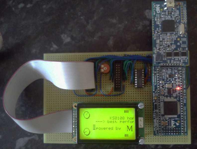
well, that was a bit of excitement! had to swap boards, toolchains & enviroment-variables...,-) here is the result: mios32_toolchain gcc-arm 4.8_20131204 lpc17 28ms 27ms stm32f4 18ms 17,8ms AND i noticed, that you are right! the trouble is, that you cant see the flickering on the lpc17, because its far too slow! i wouldnt even say, that the led on the lpc17 "flickers". its more like a "blinking". didnt realize that about 2 month ago, when i built up my lpc17-board. also the "knobs" are not rotating as smooth as on the stm32f4. so it was a misinterpretation on my side, sry, and probably the reason, why my lcd-displays are quite cheap (around 7 pounds each). dont get me wrong, i still like them, but i will look out for a replacement type with a modern controller, when i get chance. i bought them from china and would rather go for rs/farnell as a supplier, just because they are more reliable and can deliver next day (for free) as well! so i would say: problem solved! ks0108 works just fine on the stm32f4. will add some more components to my stm32f4-board in the next days. mainly sd-card, i2c and midi. we shall see... kind regards, mOnO
-
my configuration is exactly, as it should be: lcd_num_x = 1 & lcd_num_y = 1. have used the original unmodified (!) file from apps/mios32_test/app_lcd/ks0108. in this file the while() loop is executed in the background task. as far as i am concerned there are no other tasks running anyway. however i have measured the execution time of the while() loop and its 18ms on my board. maybe there is a problem with the compiler ? have used this one: http://www.midibox.org/mios32_toolchain/ and i am just downloading this one to see, if it makes a difference: https://launchpad.net/gcc-arm-embedded unfortunately the download is really slow (about 1 hour). i will re-compile the source again, once ive updated the compiler... kind regards, mOnO -
-
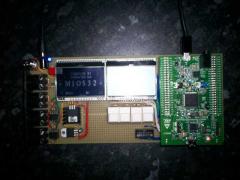
nice one! the comparison tool looks very useful... got the second display to work! the enable-signal of the second display needs to be the same as for the first one. lcd_num_x is set to 1 and lcd_width is 255, which gives me a width of 256 with 2 128-pixel-width displays. the only drawback seems to be the MIOS32_LCD_PrintString-Function. if you print the static screen in the while-loop (KS0108-Test), as it is, both displays and the four leds on the board flicker. whereas if you print the static screen before the while-loop it runs perfect without any flickering. i cant believe, that the printstring-function works slower on the stm32f4 than on the lpc17, where the ks0108-test runs without flickering out of the box. do you see any reason for that ?? kind regards, mOnO
-
ok ive tried a 3.3v voltage-regulator connected to the 3v-pin of the discovery-board and you really get 3.3volts on the lcd-pins, but it still doesnt work. so ive thought, i update the sources (again) to see what happens and voila it works with one display ! dont know what the difference between 1.014 and 1.015 is, but something magically changed... the second display still doesnt work. cs3 is connected to pc15 and cs4 is connected to pe2. have tried different parameters for lcd_num_x and lcd_width, but nothing changes. thx so far anyway...;-) kind regards, mOnO
-
lucky you are! i think you mean 0x81 (GLCD_KS0108). im still looking for the voltage-regulator...
-
board is finished so far, but the ks0108-display doesnt work. there is only crap on the screen. sometimes you can see parts of the letters, but that was it. have tested all the pins on the board and even on the display with the testlcdpin-command and it looks fine! i noticed just one problem. the 3.3v voltage is slightly below 3v. the datasheet of my display is here: http://www.topwaydisplay.com/Pub/Manual/LM12864MBC-Manual-Rev0.1.pdf it wants a minimum of 3.5v on the pins, but works fine with 3.3v on my lpc17-board. so i decided to short the diode d3 on the discovery-board to get a bit more voltage out, but with the same result on the screen. my next attempt is to use an external 3.3v-regulator, if i can find one, but the problem is surely not on your (software)-side... have you tried a ks0108-display yet ?? regards, mOnO ps. just seen your latest change to the diagram. thx for letting me know, but the problem is the same with only one display (cs1 & cs2 connected)...
-
hier ma ein tip von mir: http://uk.farnell.com/multicomp/cr-ba-3c6-180d/knob-15-7mm-black-blue-line/dp/1441138 die gibts da auch in anderen farben. wenn es etwas mehr kosten darf kann ich dir auch noch diese empfehlen: http://uk.farnell.com/mentor/4458-6317/knob-turning-setscrew/dp/1282539 für die gibts auch noch nettes zubhör, wie z.B. ne skala: http://uk.farnell.com/mentor/332-203/pointer-dial-knob/dp/1282477 grüsse, mOnO
-
alright. have updated my folder and finally i can compile the ks0108-demo-app & the updater with no errors. i suppose, i need to find a better way of organizing my files within the mios32-folder...;-) unfortunately i havent finished my board yet, but it will be finished tomorrow and i will test it straightaway. i let you know here, how it works anyway. thanks, mOnO
-
im still working on my prototype for the stm32disovery and im hoping to get this done today/tomorrow. in the meantime ive updated the mios32_toolchain for the stm32f4 and compiled the ks0108-demo-app, which compiles just fine. obviously the lcd-parameters for the ks0108 are not set yet on my board. so i wanted to set them, but compiling the bootloader-updater-application fails, because of the app_lcd/universal-driver. whenever you have chance, can you try to compile the updater for the stm32f4 ? there are too many errors and i agree that all these compiler-options are really a mess... thx, mOnO ps. ive compiled the ks0108-demo-app using the old universal-driver. with the updated version compiling fails as well...
-
hi kpete, i was just reading this: is there any reason to use 12volts ? im using the LM1085 (http://uk.rs-online.com/web/p/low-dropout-voltage-regulators/5339404/) together with this heatsink: http://uk.farnell.com/aavid-thermalloy/tv1500/heat-sink-to-220-218-14-c-w/dp/179934 theres also an lf33 for the 3.3volts without heatsink. it works fine from a 6volt power-supply and it gives you up to 3amps @ 5volts! it gets warm, but never hot. i dont know about your dc-dc-converter, but for the price of that you can get the 2 voltage-regulators and the heatsink. also theres no problem with switching noise! regards, mOnO
-
excellent! looks like its time to start building up a prototype for the stm32f4discovery. i will do that asap and let you know how it goes. the solution with the general purpose i/os is quite neat and there are still 12 lines of them available to control even more displays...;-) thx tk! mOnO
-
Im planning a prototype of the stm32f4-core using the stm32f4discovery. unfortunately i cant find any notes on J28. nothing in the diagram and nothing in the mios32-include-files either.... basically i want to connect two ks0108 lcd-displays, which will need 4 cs-signals. on the lpc17-core they are provided via J28, but theres nothing like that on the stm32f4-core. am i missing something or is this just not implemented (yet) ?? mOnO
-
ok. ive updated the mios32_lcd file and re-compiled my programm. finally all the 256 colums work, which gives me 70x8 characters on two ks0108-displays. thanks a lot for that. :rolleyes: kind regards, mOnO
-
Hi, im trying to use 2 KS0108-Displays on my LPC17-Core-Board. With the Bootloader i can setup lcd_width @255 maximum, which results in one unused column at the right side of the 2nd display. has anyone experienced similar problems and what is the workaround to get all the 256 lcd-columns working properly ?? regards, mOnO
-
excellent service! thank u very much! kind regards, mOnO
-
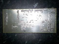
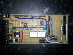
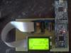
...have swapped cs1&cs2 and attached a photo of my lpc17-core. just for completing the topic. and yes, i know there is not even a voltage regulator! its my very first prototype. it has only two modified j15-connectors for two ks0108-displays. 5v are from usb and 3.3v are from the lpc-link-board. have received my 3.3v-regulators and will add them to the board. i2c and midi as well later... kind regards, mOnO
-
morning. good news! after reading your answer i measured the pins with testlcdpin again and voila had a short between the enable pin and db1. working fine now! cs1 & cs2 still need to be swapped for some reason, but apart from that im happy! can now start adding a few more interfaces (midi/i2c) and than i will dive into mios32 programming...:-) kind regards, mOnO
-
...same "rubbish" on both screen-halves. the only difference is that the led stopped flashing. cs cant be @5v according to the datasheet. it needs to toggle with the r/w change. will give up for today. i try the level-shifter somehow tomorrow and let u know how it looks like. thanks a lot so far! kind regards, mOnO
-
ok. have done that! still no valid picture. just rubbish on the left side of the screen... kind regards, mOnO
-
nice to know that the flashing is normal. unfortunately i have no access to level-shifters like u mentioned. maybe i can figure something out with an uln2803... have tried both ks0108-lcd-type (0x81/0x82). no success. i think u r right with the 3.5v. but i have used the display before on a pic32, running @3.3v! worked fine there. will meassure the voltage on the pic32 tomorrow again to confirm if thats the issue... thx. ...just tried lcd_type 0x82 (GLCD_KS0108_INVCS) and the on-board-led does not flash! i wonder why that is...
-
im trying to connect a ks0108-display to the lpc17-core. datasheet can be found here: http://www.topwaydisplay.com/Pub/Manual/LM12864MBC-Manual-Rev0.1.pdf have connected cs1 to j28-sda, cs2 to j28-sc and reset to +5v. have uploaded the ks0108-test from mios32_test/app_lcd. after rebooting the lpc the led on the board fades twices and then it just flashes. the lcd itself shows only random rubbish. first on the right side and then on the left. no data at all and no changes within the "rubbish" either. the testlcdpin command from the bootloader works fine! all pins are connected right. the only thing i noticed is that the voltage is about 3.1v instead of 3.3v on the control pins. the data lines work with 5v as expected. where could be the problem ? have used the display on a pic32 before and it worked fine. dont know how i get this to run on the lpc17. any help appreciated.... thx.