mono
-
Posts
104 -
Joined
-
Last visited
-
Days Won
2
Content Type
Profiles
Forums
Blogs
Gallery
Everything posted by mono
-
i believe, that it would be a "trivial" challenge for you, but its clearly not trivial for me. maybe at some point in the future i will try that. and who knows with which boards st will come up in the future ? But i can see from where you are coming from and i understand that the more boards can be used with mios, the more problems users could come across and managing this could end up in a "full-time" job. I had a closer look into the mios-sources and i think you could adapt any board like that. the problem is only not to loose the plot with the pins and all the macros. at the moment 1MB Flash should be more than sufficient anyway even for the "biggest" midi-applications, i can imagine. no need for 2MB Flash anyway. kind regards, mOnO
-
@m00dawg: thats exactly the problem with that board! its for prototyping only. you cant use it in a "real" product, at least not with the touchscreen. the pin-header-pins on the "touchscreen"-side of the pcb are too long or in other words higher than the touchscreen itself and no, you cant de-solder the touchscreen. no way to design a frontplate for that. there are 2 tact-switches + the jumpers as well. but apart from that i do like it. it works fine in ucvision, just for a play. it lacks the d/a-converter and the pins are a nightmare. you would have to sort them in your very own spreadsheet in comparision with f407-board for mios32 i suppose... @tk: i was thinking of that, when i bought it, but because of the reasons above, its not really worth to do that. it would be a nice challenge to port mios32 on that though... best regards, mOnO
-
@TK: if its that easy to port mios32 to a smaller discovery-board, why not porting it to the "bigger" version: http://uk.rs-online.com/web/p/processor-microcontroller-development-kits/7892815/ it costs only a little bit more than the regular F407, but for that you get a touchscreen-lcd, 2MB Flash and a few more bits... kind regards, mOnO
-
finally i got it! seems like the usb works much better on MacOS than on windows (like it is with other stuffl..). but i did exactly the same as you have described. after the reset, you have to restart mios-studio on windows, which is normal, and than the mios32-device disappeared in mios-studio. as my last resort i decided to re-install the mios32-driver and now it works a treat! i know, sometimes it can get a bit annoying to describe something, especially, if we have 2 different operating systems, but we definetely have excluded all the options to get it to run under windows. hope that will help others, who may come across the same problem and many thanks for your patience anyway... kind regards, mOnO
-
thanks for clarification! have updated my svn and re-compiled the bootloader-update-application. gcc gives now 2 warnings in usbd_req.c, but it compiles anyway. i do need that application, because after uploading a program in usb-host-mode, i have no access with mios-studio anymore, as mentioned before. the only workaround is to re-flash the bootloader with the st-link-utility, which obviously deletes all my mios-parameters. for that i need the bootloader-update-application. im using 2xdogm-graphic-lcd on my stm32f4-board, so without that i cant see anything on my displays. but when compiling the update-application with the MIOS32_DONT_USE_USB_HOST switch it still doesnt do that. have managed to change the mios-lcd-parameters after uploading the application, so it seems to work somehow, but after a storing and reseting i cant connect to mios-studio anymore... kind regards, mOnO
-
ok, that seems to work! have re-compiled the bootloader-update-application. it runs in usb-host-mode and it works in the terminal via a 2nd midi-interface. unfortunately the behringer bcr2000 is my only usb-midi-interface and it doesnt allow me to transfer sysex for the code-upload. when uploading code mios studio says: "Bootloader mode cannot be entered". looks like i need another usb-midi-interface for that..:-( also i noticed that compiling with #define MIOS32_DONT_USE_USB_HOST in mios32_config.h doesnt work. the application will still be compiled for usb-host-mode. kind regards, mOnO
-
yeah! it does work with my m-audio axiom25. power from the usb-port is not enough for that, so it will need an external power supply, but yes it works. the only problem is, that you cant use the usb-port for mios-studio anymore, because, windows cant detect it as a mios32-device, but i guess this is normal...
-
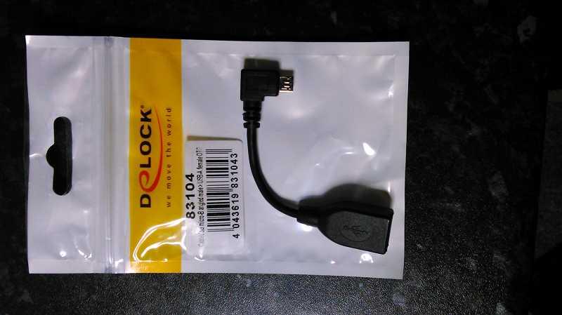
thanks tk, have done that! btw. even found a cable. its a usb-otg cable, which i bought for my nexus7. i think it will work with that. photo is attached...:D
-
looks very interesting to me! normally i would volunteer as a beta-tester, but unfortunately i havent got the usb-cable (yet). but if you want, you can send me already the beta-mios32 and then i have a reason to get one. excellent work! :D
-
...for prototyping i can highly recommend "seeedstudio". excellent service! now they even offer 4-layer multilayer and panelized pcbs for a fair price. they will check your gerber-files and ask you to re-send them, if needed. they offer a great assembly service with their open-parts-library as well, so you dont have to solder your smd-resistors onto your boards. they can do it much quicker, so you dont need to waste your time with stuff like that. lead-time is 2-3 weeks for uk. delivery is for free for orders over $50. if your pcb is cheaper than that, you can fill the order up with fancy gadgets. :D for production pcbs, i would prefer osh-park. they are in the business for quite a while. i remember seeing comparision-photos from their pcbs and they have excellent quality for higher quantities. this includes the finish, solder-mask, plating on holes. great! mOnO
-
...had the same problem before! for me the easiest way was to re-flash the mios-bootloader. i know, it sounds silly, but it does the job...:D mOnO
-
 ok thanks for the information. it was a only a thought from me... mOnO
 -
...excellent news! the duo-led-matrix-board looks quit neat. just one question: is the copper rest ring for the duo-leds big enough ? on the picture (bottom side) it looks like its too small and then it gets diffcult to solder. usually i add 30 mil to the hole-size, which gives me a 15mil copper rest-ring around the hole. with that i get good solder results. not sure how to do that in kicad, but im quite sure, that you can setup the pad-sizes somewhere. also i like the sil-header format. 10-pin is what i use for my projects as well. :D keep up the good work anyway ! mOnO
-
thank you for your information, i have to be a bit more patient for the moment, as its still in work, but it definetely looks like a very useful project for me already...:-) keep up the good work! mOnO
-
yes i got it now! this is why i think, your project is really great! i was asking for a 16-port-version (16 midi-ins/16 midi-outs), in which case i would need the fpga-board, 2 i/o-boards and 4 bobs. i think that this would fit nicely in my rack! if i would decide, that i need more than 16 ports, i would need another unit. i believe 16-ports will be the maximum for a 19-inch-device. had something like that in mind for quite a while now, but never had a real thought of it. i will keep watching here for any updates anyway. is the fpga-daughterboard the "CoreEP2C8" ? they really have a lot of interesting stuff there btw. are you planing to publish any schematics, apart from the sources for the stm32 and the fpga ?
-
thanks ilmenator for your explanation. my understanding is, that i could connect only one BOB to J11E of the stm32core, which will give me 4 midi-ports (in/out). they work already with 5v in my case. dont need the smashtv-version, as i could easily do (and want) my very own. if i would need more than the 4 midi-ports, lets say 16, i would need the fpga-board with i/o-boards, so im obviously not getting around having one fpga-board (btw is it the "CoreEP2C8" ?) and probably 2 i/o-boards + 4 bobs, right ? im fully aware, that your studio-setup requires 56 midi-ports. thats absolutely fine to me, but i was asking for a version for my setup, where 16 midi-ports should be enough for a start, as i could connect even more, if i wanted too... mOnO
-
hi ilmenator, have read the mb_matrix-wiki. looks like a really interesting project. is it designed for the "CoreEP2C8" ? i suppose you can program the fpga-daughterboard with your fpga-mainboard ? eventhough i like your modular concept, i would go for something like 2 I/O-Boards and 4 BOBs (BlitterObjects ? :D). would it be possible to connect them directly to the stm32-core ? are you planning to upload your source into the mios32-repository ? and yes as a altium-user i must admit, that i really like your kicad drawings! keep up the great work! mOnO
-
theres the difference! two different setups, which changes the way the bcr is connected to your amibika completely:
-
your last posting sounds different to your first, doesnt it ? but anyway, i would try the pic-based midi-merger as the easiest and cheapest solution. if you cant do that, just try to avoid your feedback-loop from the ambika. it has only 8 controls. dont know what they are for though, but whats the point of controlling one device with 2 sorts of controllers ? just stick to your bcr2000 and it should be alright. especially you could setup the bcr for the ambika in multiple presets and switch between them, instead of using the 8 controls from the ambika itself.... mOnO
-
...d1 (for each optocoupler ?) is there to protect the optocoupler from anything what could damage it from your midi-in. c1 should be next to the output of the voltage regulator (ic3) to give you better stabilisation and c2 should be connected to your pic (vdd/vss). its called a decoupling cap: http://en.wikipedia.org/wiki/Decoupling_capacitor most of the times you dont need it, but on a pcb i wouldnt leave them out. just in case something doesnt work as expected...
-
...in case of the bcr2000 you can forget about the diy-midi-merger! just connect your bcr-out to the ambika and your keyboard to the bcr-in. if you select midi-mode 1-3 on your bcr it will merge your data. no need for seperate (diy-) hardware! @ilmenator: the link is from a french guy. google found it for me. i suppose, if you send the odd midi-bytes every few minutes/hours, the "simple" midi-merger will work a treat. otherwise it will fail, because it will "shuffle" the midi-bytes around...:D mOnO
-
hi stefanovic, i dont think, that it would be better to get the power from midi. its an isolated connection. theres no ground from the transmitter to the receiver and no power from either device. i dont even believe, that your midi-solutions-merger works at all. the list of unsupported devices is quite long. yes, maybe some devices will work, but that would be by "accident"... for a start i suggest you this easy one without mcu: http://www.sonelec-musique.com/images/electronique_midi_merger_001.gif if you want a better one read here: sry. didnt find further information on ucapps.de, but "something like that" is definetely a better solution for a midi-merger in my opinion. if you dont feel "that knowledgeable in electronics" look out for this: http://www.doepfer.de/mmr_e.htm yes, i know, its sold out, but maybe you can find it somewhere on the 2nd hand market... :D kind regards, mOnO edit: here is something "made in uk": http://www.thomann.de/gb/kenton_midi_merge.htm
-
hi soj, another good example for a plastic case is here: http://www.sonic-potions.com/ very neat design and excellent quality. 6 pieces of laser-cut material in total. design is very similar to the ambika. you can find a good service for a fair price here: http://www.seeedstudio.com/service/index.php?r=st/lasercutting mOnO
-
hi mwpost, na sieh ma an! da kommen wir der sache doch schon einiges näher... die mios-verbindung in deinem ersten bild ist die verbindung von der mios-firmware zu deinem rechner (MIOS32-Treiber). dieser dient z.b. zum upload deiner "programme". desweiteren haste über diese usb-verbindung auch 1xmidi-in und 1x-midi-out zur verfügung, was ja prima funktioniert! wenn du nun diese verbindung kappst, ist natürlich automatisch der midi-treiber pfutsch und somit kommt keine verbindung zu mios-studio mehr zustande. ergo is das zweite bild ebenfalls richtig und sollte auch so sein! die verbindung zum midi-interface is aber nach wie vor da. also musste schon mit nem midi-monitor, oder nem ähnlichen programm, zb. midi-ox, die midi-ports deines midi-interfaces loggen und dann sollte da eigentlich was vom board ankommen. wenn da nix ankommt, musste mit der midi-configuration deinen bevorzugten midi-port wählen und das programm halt nochma kompilieren, bevor du es über deine usb-verbindung (!) zum board hochlädst. hoffe, daß war jetzt halbwegs narrensicher...:-) lg, mOnO ps. die widerstände für die midi-ports sind ganz schön "beefy", oder 8-.
-
...nachdem du nun die 5v tatsächlich anliegen hast und auch deine weitere "verkabelung" (mit sicherheit) ein paar mal überprüft hast, würde ich an dieser stelle ma ein hardwareproblem ausschliessen. midi-interface is meiner meinung nach auch unkritisch. zumindest hats bei mir mit allen möglichen geräten geklappt. nun zur nächsten "falle". was heisst denn "du bekommst kein signal über die midi-ports" ?? heisst das, daß du dein board nicht mit mios-studio verbinden kannst, oder versuchst du einfach nur irgendwelche midi-daten zu senden/empfangen ?? mOnO PS. mach doch ma ein foto von deiner "konstruktion"! hier is meine: