mono
-
Posts
104 -
Joined
-
Last visited
-
Days Won
2
Content Type
Profiles
Forums
Blogs
Gallery
Everything posted by mono
-
...jetzt verstehe ich! die 2,9V kommen von dem spannungsregler auf dem discovery-board. das ist so ne eigenart. speziell meine ich da u1 (ld3985) auf seite 36 im discovery-user-manual (UM1472/DM00039084.pdf). wenn man da echte 3,3v braucht, gehts mit dem ne, da der halt 3v ausgibt! habe bei meinem ersten discovery-versuch aber selbst mit ner sd-karte und dem intergrierten spannungsregler keine probleme gehabt! meine discovery-boards sind ebenfalls mit mb997c beschriftet. daran kanns schonma ne liegen! aber was mir komisch vorkommt ist, daß vdd an die 2,9v angeschlossen ist. besser wären dort die 5v! damit erklären sich automatisch auch die 2,9v an den anderen pins. probiers ma mit vdd=5v! mOnO
-
hi mwpost, das am rx-in 5v anliegen is ja schonma postiv, da der ja von r18 gegen die 5v gezogen wird. die anderen 5v sollten aber ebenfalls anliegen, da der pin von r22 ebenfalls gegen die 5v gezogen wird. infsofern würde ich den fehler am ehesten ma dort suchen. vermutlich hast du aber auch einfach die beschaltung der midi-buchsen vertauscht. habe leider noch keinen schaltplan dafür gezeichnet, aber ich versuchs ma in textform: __1 A__2 __3 B__4 __5 Ansicht von oben auf die midi-buchse. also dein stecker kommt von links MIDI-OUT: 2 = R21, 4= R22 MIDI-IN: 2 = IC4(Pin3), 4 = R20 Die Masse am Pin 3 hab ich übrigens weggelassen, da an der anderen seite ja ein midi-out von nem anderen gerät hängt. an dessen midi-out ist die masse ohnehin nicht angeschlossen, so daß man auch einfach drauf verzichten kann. mOnO
-
well, i know that the matrix approach is a good option, if you want to read switches or output to leds in a very quick manner on midibox, not only because of the dma-controller of the stm32f4, but also because of how it is supported by mios32. When i was looking at the diagram for the first time, i couldnt figure out straightaway, how to that in a way, i described before. i will certainly keep that in mind, when i do my next design for buttons/leds. in the meantime i would appreciate any suggestions on doing this anyway...:-) mOnO
-
makes sense to me! the only problem with that solution i see is, that i would never pay for one pcb with 16 rotary-switches! this sounds really expensive to me! i would split the design into 4 pcbs with 4 rotary switches each, as i have done before. that way you keep the pcb cheap and you can use the pcb 4 times. with the price of one rotary-switch of more than 7pounds i wouldnt do it without a cnc-drilled pcb. that would be a waste of money for the switches, if you think about it, because you would never get the switches aligned perfectly straight. if anyone has an idea how to use the dio_matrix in combination with 4 pcbs a 4 switches, which can easily connected to a midibox-core, im quite happy to take the "digital way" for my next design...:-) mOnO
-
...thanks for pointing me in the right direction! looks really interesting and i didnt see that before...
-
am i missing something ? 12 inputs from 12 switch-contacts -> 12 inputs on the shift-registers = 1 (8-input) shift-register + 0,5 (4-input) shift-register. and theres i no way around, unless you are on about connecting the switch contacts in some kind of matrix form to the shift-registers...
-
i fully understand that, but you would still need 1,5 shift-registers per switch and you cant chain them that long, depending on the amount of other stuff you have to connect to the 3 processor-inputs for the din-chain. lets agree, that you could use either the digital or the analog-way. so theres plenty of room for "matcom3" to decide whichever is the easiest to go... :D mOnO
-
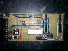
die vorgehensweise, die midi-beschaltung einfach vom lpc17-core zu übernehmen, kann ich nur bestätigen. habe vor ner weile ma mit nem layout fürs stm32f4 angefangen, aber leider habe ich momentan keine zeit, das fortzuführen. deshalb hier nur ma ein "foto" von dem, was ich bereits habe. in dem fall gibts einen midi-ausgang und 2 midi-eingänge. könnte man aber locker auf 4 ein- und 4 ausgänge erweitern, wenn man das nur wöllte... mOnO
-
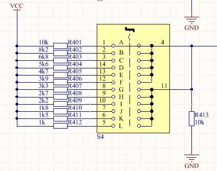
@all: i was talking about a practical circuit to give an easy solution for the problem. it was not meant to be a start for a scientific / philosophical discussion about voltage dividers and stuff. @kpete: thanks for that! this is exactly what i meant in my first posting. the resistor values are e12s. the difference between each step is big enough for the software to determine, which one out of 12 steps is selected. the absolute value doesnt matter at all and it has nothing to do with the cc-value, that you want to send either. also i cant understand, why theres a capacitance on the analog-input / switch-output. in my diagram you can clearly see the 10k resistor pulled down (!) to GND. this ensures that, if the switch is between 2 contacts, the voltage on the analog input is pulled down (!) to GND. no open inputs, no capacitance, just GND. obviously the software needs to detect this and shouldnt send anything in that case. i know, that it sounds a lot to use 13 resistors for one switch, but the benefit is, that only 1 analog input is needed per switch. in my case ive even connected these switches to analog multiplexers, that is 8 rotary-switches per analog-input. so theres plenty of rotary-switches you could connect to one mcu or in other words loads of money to spend on these switches. @matcom3: in a practical use, i would go for smd-resistors anyway. for the smt-machine its quite easy to place 13 0805-resistors per switch "somewhere" near the switch, so i didnt worry too much on that. have built a prototype with 16 rotary-switches. it took me a while to solder more than 200 through-hole-resistors only for the rotary-switches, but im very pleased with the result. it works just fine and you get a very neat "vintage" feel with them. apart from that 12 switch-positions are exactly the amount of keys per octave and you cant beat that feeling with any rotary-encoder..:D mOnO
-
i agree, that in theory there will be differences between the resistors. the resistors will have tolerances as well. the ones ive used are 5%, but ive choosen the 12 resistor-values for a good reason. if you start with the first switch-position, the next position will give you a value, that is much greater then the one before. the absolute value of the switch-position doesnt really matter as long as your program can determine one of the 12 switch-postions! from that you can calculate your desired cc-value...;-) mOnO
-
sounds like a waste of inputs to me. cant see where the problem with my solution is either. the rotary switch is connected just like a poti. to be fair it is rather annoying to solder 12 different resistors for one switch, but it works a treat! @matcom3: nice to know and please keep posting your results here... :D mOnO
-
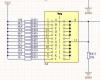
hi matcom3, i believe ilmenators solution would work, but as you want to use rotary switches, encoders are not the proper solution for you. had the same problem before and have attached a part of the diagram from my project. you can find further infos, including pictures of my pcbs, using rotary switches, here: http://www.chipkit.net/forum/viewtopic.php?f=15&t=2561 i made this before i came across midibox, but it will still work with that. the idea is to use the rotary switch as part of a voltage divider. the output of the switch has to be connected to an analog input. because the switch-output is pulled down to GND as well, you wouldnt have the problem with "open" analog-inputs. you need to modify your program to read out the switch, so it doesnt accept 0v between 2 switch-positions. worked fine for me...:-) another problem, i see with your idea, are the switches itself. depending on the money you want to spend for your project, you might be better off with these ones here: http://uk.rs-online.com/web/p/rotary-switches/0327901/ dont know where you are from, but rs is available literally everywhere. ok they are a bit more expensive then yours, but i cant advise you to use yours. have tested them before, but they are really a waste of money in my view. also you cant mount them really on a pcb, can you ?? :D kind regards, mOnO
-
various photos from my STM32F4-Boards
-
-
-
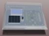
...if it has stored, it should work. i never came across that issue. i am using the stm32f4 at the moment, but i have used the lpc1769 before, both under windows7. maybe someone else can help ?? saving every pixel was the goal with the tiny font, which i have "designed" in excel. for my current project i will probably use the tiny font on a dogm128x64 display. if i get chance i will "design" an inverted version of the tiny font for my project as well. if you like the tiny-font, let me know, and i can update the mios-svn with the inverted tiny-font... mOnO
-
...the operating system shouldnt be the reason for your issue. it sounds more like you havent stored the lcd-parameters with the bootloader application. try that first. also you should try the tiny-font: MIOS32_LCD_FontInit((u8 *)GLCD_FONT_TINY); which gives you the maximum amount of letters on your display. if your compiler cant find the tiny-font, update your mios-sources... mOnO
-
...glad to hear, that you are happy now! mOnO
-
hi istel, very adventurous construction btw... anyway first i would change the display-driver in ~/.profile from uc1610 to universal and re-compile everything. next i believe, that pin26 is connected to GND instead of 3.3v. the 100nF cap on pin17 is missing, whereas it should work without that, and im not really sure about the other caps. if you have used electrolytic caps, as it looks to me, make sure the polarity is right, otherwise it cant work... mOnO
-
hi scrubber, forget these ebay-pic-programmers! get the pickit2 http://uk.rs-online.com/web/p/processor-microcontroller-development-kits/0381582/ along with the pic itself http://uk.rs-online.com/web/p/microcontrollers/4672126/ and just do it! they even offer an excellent next day delivery service, with the right preparation you can get it up and running by the end of the week and you could buy/program as many pics as you want as well...:-) mOnO
-
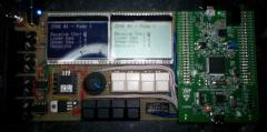
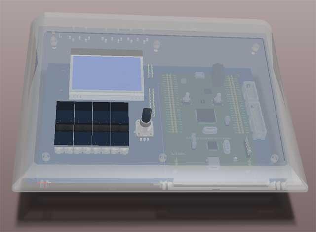
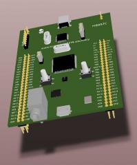
From the album: STM32F4-MoNo
final version of the prototype with more buttons and an encoder...© mOnO
-
...it is correct, if you want to connect MIDI-Port1 (LPC) to MIDI-Port1 (STM32F4), so you should be able to receive midi with your lpc from the stm32 and receive with your stm32 from the lpc... mOnO
-
...another reason for using pin-headers for me was, that i had to try all these fancy backlights in combination with all these fancy displays. with the right type of header you dont even need to solder the display on the backlight. my favourite is the white backlight under the negative display (order-code S). love it..:-)
-
hi istel, sry, forgot about the RESET. just connect that to Vdd (3,3volts). all the other pins as described before. i wouldnt use a ribbon cable. have placed my dogm-lcd on sockets on the pcb: this way u can re-use them for other projects. they are really good, but still expensive... mOnO
-
hi, your display seems to be a new dog-variant. but if u stick to the 4-wire-spi-diagram on page4 and 3.3volts, i cant see a problem with that. you would only need 2 caps 2uF and 1 100nF. this is what i would do: SDA - SI - J15A/RW SCK - CLK - J15A/E CD - A0 - J15A/RS CS - CS - J15A/D0 (for the 1st display) use the dogm-glcd-driver in the bootloader-configuration and set your resolution to 160x104 px AND dont forget to post, if it works...:-) mOnO
-
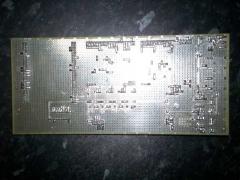
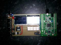
...after seeing a few prototypes of other stm32f4-core-boards i decided to upload a few photos from my board. it uses 2 dogm-glcd-displays, 2 midi-ports, 4 j10-buttons and the sd-card-connector... heres the top-view without any modules: and here the bottom-view: cheers, mOnO