

mono
-
Posts
104 -
Joined
-
Last visited
-
Days Won
2
Content Type
Profiles
Forums
Blogs
Gallery
Everything posted by mono
-
thanks for advising me. regards, m0n0
-
hi marxon, is the gm5 driver for the lpc-board, if its not needed for the stm32 ? mOnO
-
http://ucapps.de/mios32_download.html under "drivers" you can find the windows-drivers for mios32. make sure to pick the right one for you os. if it still doesnt work try uninstalling and re-installing... regards, mOnO
-
electrodancer, looks like a driver issue to me. try re-installing the correct version and then it should connect. if it doesnt, the problem is on your side...;-) regards, mOnO
-
hi bernds, im prinzip kannst du jeden widerstand von den 12 für die 6 schalterstellungen nehmen. nur macht es sinn mit 1k zu beginnen und mit 10k aufzuhören. die 4 werte dazwischen halt "irgendwie" aufsteigend, natürlich aus ner recht groben e-reihe. den daraus resultierenden spannungswert musst du eh erst erstma mit deiner mcu nachmessen und dann halt deine software dementsprechend konfigurieren. je weiter die widerstände auseinanderliegen, umso bedeutungsloser wird der reale widerstandswert, sprich umso gröber dürfen deine widerstände toleriert sein und umso billiger wird die konstruktion. :rolleyes: mfg, mOnO
-
hi bernds, gehe ma davon aus, dass du den 12-stufigen schalter verwenden willst (DS1 bei reichelt). in diesem fall gehst du folgendermassen vor: http://fs1.directupload.net/images/150208/p87bal3a.jpg A ist einer der mittleren kontakte. sieht so aus, als ob es egal ist welcher. bei 2 pol. schaltern sind dann halt 2 paare an kontakten vorhanden für jeweils 6 schalterstellungen. 1-6 / 7-12 diese kann man halt an 2 geräte anschliessen oder auch nur einen davon verwenden. ähnlich ist es mit 3 oder 4 ausgängen (siehe datenblatt). ich hoffe das hilft dir weiter... mfg, mOnO
-
ok bernd, wenn du mit mit meiner beschreibung nicht klarkommst, kann ich auch gerne nochma einen kleinen schaltplan speziell für deinen drehschalter posten, wenn du mir die genaue typenbezeichnung gibst. lass es mich einfach wissen! mfg mOnO
-
...as i said, you need the filter, when using a "slow" cpu. with slow i wasnt refering to the stm32 or the lpc17, that mios32 runs on. both are anything else than slow! it was rather a general question about encoders and a general answer. try connecting different encoder-types with a small 8-bit pic or atmel and you will see, what happens with and without the filter. :-) regards, mOnO
-
hi novski, short answer: YES! personally i cant see the point of having r5 & r6 in the circuit. this will only half the values of r3&r4 (?). 10k for r3&r4 (pullup) is alright anyway. for the filter itself i would decrease the c1&c2 values to 10nF. the encoder impulses are very short and i dont think that you get decent results with 100nF. btw. im always connecting encoders with this additional filter. this way i can use the cheapest encoder and still get good results, even if the cpu is slow...:-) regards, mOnO
-
hallo bernds, kenne mich mit deiner "doepfer-kiste" auch nicht aus, aber du kannst den schalter auch als schaltbaren spannungsteiler an einen der potentiometer-eingänge anschliessen. habe auf diese weise bereits 12-stufige drehschalter bequem zum "laufen" bekommen. an die 6 schalterpositionen hängst du einfach 6 widerstände, zb. 1k, 2k2, 4k7, 6k8, 10k, die mit vcc verbunden sind. an den gemeinsamen anschluss schliesst du einfach deinen doepfer-potentiometer-eingang und einen weiteren widerstand (10k) gegen masse. vcc dürfte so bei standard 5v liegen. auf diese art brauchst du nur einen eingang pro schalter. selbstverständlich kann man auch mehrere schalter gemultiplext an einem eingang betreiben, aber da ich deine "doepfer-kiste" nicht kenne, kann ich dazu wenig beitragen... mfg, mOnO
-
yes, these are actually commands for the update-application. once you have stored these parameters you wont need the update-applciation anymore, because you have stored them on the discovery-board. your mios-applications can read them out and the functions will work accordingly... :shifty: best regards, mOnO
-
...seems to be a standard-lcd-module. have you done the lcd-configuration in the bootloader-update-app ? if not you can even test the lcd-signals there... best regards, mOnO
-
...even an arduino would do! the pic16f84 has no a/d converters built in, whereas the arduino comes with 6 10-bit a/d-converters + usb. also the pic is not that easy to program, unless you have the pickit (or something similar) already. overall i would say, that midibox for a single channel is a bit "over the top"...;-)
-
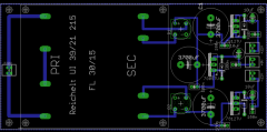 ok. waren auch nur so meine gedanken als ich das layout gesehen hatte. auch habe ich grad erst bemerkt, daß das photo schon älteren datums ist...;-)
 -
hi acul, hier mal meine gedanken zu deinem design: die klemme am eingang erscheint mir zu klein. da dort ja immerhin 230v anliegen, wäre es vernünftiger eine klemme mit größerem pinabstand zu verwenden. auch eine sicherung nach der klemme könnte nicht schaden. desweiteren vermisse ich kühlkörper an sämtlichen spannungsreglern! ok. selbst wenn die zu erwartende ausgangsstromstärke nicht allzu hoch ausfällt, werden sich die spannungregler trotzdem noch um einiges aufheizen. insofern ist man mit wenigstens einem kleinen kühlkörper immer gut beraten. die dioden über den ein/ausgängen der spannungsregler kannste dir aber sparen, da diese in den meisten spannungreglern bereits eingebaut sind (siehe datenblatt). das problem mit der bauhöhe könntest du lösen, indem du einfach kleinere elkos am eingang der spannungsregler verwendest. der von dir verwendete trafo bringt ohnehin max.1A. als faustregel für diese "einfachen" spannungregler gilt: pro 100ma stromaufnahme am ausgang, 100uF elko am eingang. in deinem fall würdest du sozusagen locker mit nem 1000uF (entsprechend für 1A) auskommen und dieser wäre dann auch kleiner. auch hängt die höhe vom trafo natürlich von der zu erwartenden stromstärke ab. vielleicht reicht ja auch ein kleinerer typ ? ;-) in diesem sinne mOnO
-
...description is wrong, so you might be eligable for a refund or you just keep it and get another one. its an excellent price for the f429 btw., but unfortunately mios is not ported (yet) for that board, as discussed before... alternatively, for that price you could do all of us a favour and send it to tk 4free! :-) kind regards, MoNo
-
 @john: thanks! like your wiki regarding fonts as well! the only thing that i dont get are all these seperate programs for drawing and converting. this is why i have made my own in excel. its nothing complicated either! the first column is the ascii-code (hex), the 2nd is the character in a normal font, the 3rd is the character taken from a truetype-font, then the pixel-drawing (done with conditional formatting) plus the bits for the code. they are then just added binary into decimal and the last column tells you the hex-value. no need for seperate programs... i cant upload that spreadsheet now, because it contains much more "private" stuff, but i will upload an example tomorrow. i have done characters for dot-matrix-displays with excel as well! the point is, that normal lcd-characters are small and i believe using a "paint"-like program for that is a bit over the top. i have done similar stuff on my amiga about 20 years ago. the converting bit is just not worth the hassle, especially because theres only one bitplane on lcds :-) . with excel you get exactly, what you want. you simply copy the last column into a text-editor of your choice :-) and make up your include-file for the compiler. eg. im using sublime-text, which comes with macro-functions to do this type work. kind regards, mOnO
 -
...heres one more tip from me: instead of using hundreds of programs for thousands of uses, stick with one program that is more versatile! eg. for creating icons/fonts use a spreadsheet. attached is an example of how i create fonts in excel. no converting issues, no looking for converters, etc...its really great for all sorts of code-related stuff, in fact any spreadsheet will do the job...;-)
-
...not sure, if we are talking about the same board then. u5 is the mems-sensor on page 36 of the discovery-manual. u5 is not getting 2v5 at all! its u7, the audio-codec, that needs the 2v5. but if you have removed c1 and c20 already, i cant see, where the short comes from. hopefully you have ordered not just one discovery-board! i have 2 of them which i use with different configurations, as im using different lcd-types. the other advantage of that is, that you have always one on the shelf in case the other gives up..:-) kind regards, mOnO
-
4ohms between 5v and gnd sounds strange to me! but eventhough u1 and u3 are low-drop-regulators, they are not affecting the 5v rail, as they are 2,5/3v regulators. i would suspect c1 or c20 (next to u1/u3) to be destroyed from your "high voltage". these are the only ones, that could cause the "short". you can try to desolder them or even replace them, but for the price of the board, its not worth the hassle anyway...
-
thanks for testing this. the method of "mixing" the colors is exactly, what i mentioned before. it gives you 7 colors + 1, which would be "off". have attached a photo of my prototype for 2 of these rgb-modules using an arduino. its basically the same as yours. i couldnt really believe, that you could do full-rgb with the 595s. they are just too slow to do the pwm. this is why i mentioned the tlc5940 for full-rgb... kind regards, mOnO
-
thanks for clarification! had a look at the wiki and theres nothing said about the color-resolution. furthermore the colors in the provided photos look like full-rgb to me and i wasnt sure if yours is full-rgb or not. presumably the 595s are too slow to do full-rgb, even if the stm32f4 wouldnt be too slow... kind regards, mOnO
-
hi karl, actually there was a discussion regarding the stm32f4F429 last week in another thread: much appreciated, if you volunteer to implement that on mios32...;-) kind regards, mOnO
-
...forgive me if i was wrong, but have found sources for the blm-x-module and it looks like it works already with pwm. is it possible, that your rgb-module already works in full-rgb ? and if so, which kind of color resolution do you get on the stm32f4 ? kind regards, mOnO
-
nice job! love the pcb-layout. its has exactly the right size to chain them together horizontally! the design itself with the 595s is kept very simple, so you have only 7 (8) colors per LED, which is enough for most applications and i suppose the software for that is really easy to do on mios32. i have done similar stuff on atmel controllers before. would be nice to have a full-rgb-version similar to that. the tlc5940 is ideal for full-rgb. it would give you 12bit-colors (4096) per led... kind regards, mOnO