

Phatline
-
Posts
1,285 -
Joined
-
Last visited
-
Days Won
72
Content Type
Profiles
Forums
Blogs
Gallery
Posts posted by Phatline
-
-

a lot of pictures of the build, some explaination:
http://wiki.midibox.org/doku.php?id=scale-explorer#teaser
some coding and real world jamsession has to be done the next months, so i dont uploadet a code yet...
What it does shortly:
Indicate via LEDs over the Keys, what Notes fit to the actual set Scale.
I preprogrammed 240 scales, when i change the root note (on the fly) this are 2400 or more scales...
programming scales, and songs is easy - just play a melody! or connect your sequencer in feed Scale-Explorer with your song! (root +2 +2 + 3+ 3+ is a scale for example... but it dont matter in which order you press it, my code detect its order)
so you can indicate what scales, or notes you use in your song, or indicate what your Jaming Partner is playing on is Gitarsynth or Keyboard or Sequencer (in the case you dont hear notes as "notes" like me!)
the songmode, is a "always recording" one, that means, you hit record after you played what you wanted to record... its more easy to not "try and try and try to make a perfect record" just jam, and when you think - whoo hoo that was awsome! press Record, set the loop points (which in length are always multiples of the set tact 4/4 leading into 4 8 16 32... 3/4 to 3 6 12 24...) and maybe press "purge" to clean not used notes and to shift it to Step 1...
8 Songs per scale are possible
128 scales are saved on one preset which can be loadet from sd-card, each scale can hold 8 songs/song parts, which is saved as 1 song on the SD-Card, that song is automaticly loaded by changing a scale....
So the SD-Card is pretty full with songfiles...
There is a Trigger Amplifier and Schmitt trigger built in (Konga Trigger), which retrigger the pressed Keys, or Trigger Songsteps and go to the next song step while you can hold a step with Footswitch or Reset the Song to Jump to Step 1...
Last Jamsession, i was sitting on this Wood-SnareDrum Instrument, clamped the trigger mic on the bassreflex opening, recordet a short snipped of the keyboard a other person played, and began to play the base, snare and "Wood" part of this 8 man Jamsession, in short time i was leading the thing, because Snare Wood Bass and its melody was fitting in this environment... i loved it! i am not a good drummer, or keyboard, but this for me was the holy grail, Electronic Music with real Humans instead of clock driven sequencers...
i hope i can get you a video next month!
Prepgrammed scales are: (thy have also names, but that would a bit to much for this post ;)
// SCALES
s8 new_scale[Nr_off_Files][128][13] = {
{ //File 0
{1,1,1,3,1,2,1,0,0,0,0,0,0},{1,1,2,2,2,2,0,0,0,0,0,0,0},{1,4,2,2,0,0,0,0,0,0,0,0,0},{1,7,2,0,0,0,0,0,0,0,0,0,0},{1,1,2,1,2,1,2,0,0,0,0,0,0},{4,4,0,0,0,0,0,0,0,0,0,0,0},{1,2,4,1,0,0,0,0,0,0,0,0,0},{1,1,3,2,1,2,0,0,0,0,0,0,0},//0
{1,2,1,2,1,2,1,0,0,0,0,0,0},{1,1,1,1,1,2,1,2,0,0,0,0,0},{1,1,1,2,1,1,1,2,0,0,0,0,0},{1,1,2,1,2,3,0,0,0,0,0,0,0},{1,2,1,3,1,2,0,0,0,0,0,0,0},{1,1,3,2,2,1,0,0,0,0,0,0,0},{1,1,3,2,3,0,0,0,0,0,0,0,0},{1,1,2,1,2,2,1,0,0,0,0,0,0},//1
{1,1,3,2,1,1,0,0,0,0,0,0,0},{1,1,2,2,1,2,0,0,0,0,0,0,0},{2,2,3,2,0,0,0,0,0,0,0,0,0},{1,1,1,2,1,2,1,1,0,0,0,0,0},{1,2,3,2,2,0,0,0,0,0,0,0,0},{1,1,1,2,2,1,2,0,0,0,0,0,0},{1,1,1,1,3,3,0,0,0,0,0,0,0},{1,1,1,1,1,1,1,1,1,0,0,0,0},//2
{1,1,1,1,1,1,1,1,2,0,0,0,0},{3,3,3,0,0,0,0,0,0,0,0,0,0},{3,9,0,0,0,0,0,0,0,0,0,0,0},{4,8,0,0,0,0,0,0,0,0,0,0,0},{2,2,2,3,0,0,0,0,0,0,0,0,0},{1,2,2,1,3,0,0,0,0,0,0,0,0},{1,1,2,1,3,2,0,0,0,0,0,0,0},{1,1,1,1,1,1,1,1,0,0,0,0,0},//3
{1,1,1,1,1,1,1,2,0,0,0,0,0},{1,1,1,1,1,1,1,3,0,0,0,0,0},{1,1,1,1,1,1,2,1,0,0,0,0,0},{1,1,1,1,1,1,3,1,0,0,0,0,0},{1,1,1,1,1,2,1,1,0,0,0,0,0},{1,1,1,1,1,3,1,1,0,0,0,0,0},{1,1,1,1,2,1,1,1,0,0,0,0,0},{1,1,1,1,1,1,2,2,0,0,0,0,0},//4
{1,1,1,1,2,1,1,2,0,0,0,0,0},{1,1,1,1,2,1,2,1,0,0,0,0,0},{1,1,1,1,2,2,1,1,0,0,0,0,0},{1,2,2,2,2,0,0,0,0,0,0,0,0},{2,2,3,0,0,0,0,0,0,0,0,0,0},{1,2,2,2,3,0,0,0,0,0,0,0,0},{1,1,1,3,1,3,0,0,0,0,0,0,0},{2,3,2,0,0,0,0,0,0,0,0,0,0},//5
{1,2,2,2,1,0,0,0,0,0,0,0,0},{1,3,1,3,1,0,0,0,0,0,0,0,0},{1,1,2,1,3,1,0,0,0,0,0,0,0},{1,1,3,1,3,1,0,0,0,0,0,0,0},{1,1,2,2,2,1,0,0,0,0,0,0,0},{1,1,3,1,2,1,0,0,0,0,0,0,0},{1,1,3,1,2,2,0,0,0,0,0,0,0},{1,2,1,2,2,1,0,0,0,0,0,0,0},//6
{1,1,1,1,1,2,2,1,0,0,0,0,0},{1,1,1,2,3,1,1,0,0,0,0,0,0},{1,1,2,1,1,3,1,0,0,0,0,0,0},{1,1,1,1,2,2,1,0,0,0,0,0,0},{1,2,1,4,2,0,0,0,0,0,0,0,0},{1,1,1,1,1,1,0,0,0,0,0,0,0},{1,1,1,1,1,2,0,0,0,0,0,0,0},{1,1,1,1,1,5,0,0,0,0,0,0,0},//7
{1,1,1,1,2,1,0,0,0,0,0,0,0},{1,1,1,1,5,1,0,0,0,0,0,0,0},{1,1,1,2,1,1,0,0,0,0,0,0,0},{1,1,1,5,1,1,0,0,0,0,0,0,0},{1,1,1,1,1,3,0,0,0,0,0,0,0},{1,1,1,1,1,4,0,0,0,0,0,0,0},{1,1,1,1,3,1,0,0,0,0,0,0,0},{1,1,1,1,2,2,0,0,0,0,0,0,0},//8
{1,1,1,1,2,4,0,0,0,0,0,0,0},{1,1,1,1,4,2,0,0,0,0,0,0,0},{1,1,1,2,1,2,0,0,0,0,0,0,0},{1,1,1,2,1,4,0,0,0,0,0,0,0},{1,1,1,2,4,1,0,0,0,0,0,0,0},{1,1,1,4,2,1,0,0,0,0,0,0,0},{1,1,2,1,1,2,0,0,0,0,0,0,0},{1,1,2,1,1,4,0,0,0,0,0,0,0},//9
{1,1,2,1,2,1,0,0,0,0,0,0,0},{1,1,2,1,4,1,0,0,0,0,0,0,0},{1,1,1,1,2,3,0,0,0,0,0,0,0},{1,1,1,2,1,3,0,0,0,0,0,0,0},{1,1,1,2,2,3,0,0,0,0,0,0,0},{1,1,2,3,2,1,0,0,0,0,0,0,0},{1,1,1,1,1,0,0,0,0,0,0,0,0},{1,1,1,1,2,0,0,0,0,0,0,0,0},//10
{1,1,1,1,6,0,0,0,0,0,0,0,0},{1,1,1,2,1,0,0,0,0,0,0,0,0},{1,1,1,6,1,0,0,0,0,0,0,0,0},{1,1,2,1,1,0,0,0,0,0,0,0,0},{1,1,1,1,3,0,0,0,0,0,0,0,0},{1,1,1,1,5,0,0,0,0,0,0,0,0},{1,1,1,3,1,0,0,0,0,0,0,0,0},{1,1,1,5,1,0,0,0,0,0,0,0,0},//11
{1,1,3,1,1,0,0,0,0,0,0,0,0},{1,1,1,1,4,0,0,0,0,0,0,0,0},{1,1,1,2,2,0,0,0,0,0,0,0,0},{1,1,1,2,5,0,0,0,0,0,0,0,0},{1,1,2,1,2,0,0,0,0,0,0,0,0},{1,1,2,1,5,0,0,0,0,0,0,0,0},{1,1,2,2,1,0,0,0,0,0,0,0,0},{1,1,2,5,1,0,0,0,0,0,0,0,0},//12
{1,1,5,1,2,0,0,0,0,0,0,0,0},{1,1,5,2,1,0,0,0,0,0,0,0,0},{1,1,1,2,3,0,0,0,0,0,0,0,0},{1,1,1,2,4,0,0,0,0,0,0,0,0},{1,1,1,3,2,0,0,0,0,0,0,0,0},{1,1,1,3,4,0,0,0,0,0,0,0,0},{1,1,1,4,2,0,0,0,0,0,0,0,0},{1,1,1,4,3,0,0,0,0,0,0,0,0},//13
{1,1,2,1,3,0,0,0,0,0,0,0,0},{1,1,2,1,4,0,0,0,0,0,0,0,0},{1,1,2,3,1,0,0,0,0,0,0,0,0},{1,1,4,3,1,0,0,0,0,0,0,0,0},{1,1,1,3,3,0,0,0,0,0,0,0,0},{1,1,2,4,2,0,0,0,0,0,0,0,0},{1,2,2,1,2,0,0,0,0,0,0,0,0},{1,1,2,3,3,0,0,0,0,0,0,0,0},//14
{1,1,3,2,2,0,0,0,0,0,0,0,0},{1,1,3,3,2,0,0,0,0,0,0,0,0},{1,2,3,1,3,0,0,0,0,0,0,0,0},{1,0,0,0,0,0,0,0,0,0,0,0,0},{1,0,0,0,0,0,0,0,0,0,0,0,0},{1,0,0,0,0,0,0,0,0,0,0,0,0},{1,0,0,0,0,0,0,0,0,0,0,0,0},{1,0,0,0,0,0,0,0,0,0,0,0,0} //15
},
{ //File 1
{1,1,2,3,1,2,0,0,0,0,0,0,0},{1,2,1,2,1,0,0,0,0,0,0,0,0},{1,4,2,3,0,0,0,0,0,0,0,0,0},{5,0,0,0,0,0,0,0,0,0,0,0,0},{1,4,1,4,0,0,0,0,0,0,0,0,0},{1,2,1,2,1,2,0,0,0,0,0,0,0},{2,5,0,0,0,0,0,0,0,0,0,0,0},{1,2,2,3,2,0,0,0,0,0,0,0,0},//0
{1,2,1,2,2,2,0,0,0,0,0,0,0},{1,1,1,2,2,2,1,0,0,0,0,0,0},{1,2,2,5,0,0,0,0,0,0,0,0,0},{1,2,2,1,2,2,0,0,0,0,0,0,0},{1,1,2,2,1,2,1,0,0,0,0,0,0},{1,0,0,0,0,0,0,0,0,0,0,0,0},{1,0,0,0,0,0,0,0,0,0,0,0,0},{1,0,0,0,0,0,0,0,0,0,0,0,0},//1
{1,2,3,2,0,0,0,0,0,0,0,0,0},{1,2,4,2,0,0,0,0,0,0,0,0,0},{1,1,1,1,1,2,1,1,1,0,0,0,0},{1,1,1,2,3,1,0,0,0,0,0,0,0},{1,1,1,3,2,1,0,0,0,0,0,0,0},{1,1,1,3,1,2,0,0,0,0,0,0,0},{1,1,2,2,1,1,0,0,0,0,0,0,0},{1,1,1,4,1,1,0,0,0,0,0,0,0},//2
{1,1,2,2,3,1,0,0,0,0,0,0,0},{1,1,4,1,2,1,0,0,0,0,0,0,0},{1,1,1,4,1,2,0,0,0,0,0,0,0},{1,1,1,1,4,1,0,0,0,0,0,0,0},{1,1,1,2,2,2,0,0,0,0,0,0,0},{1,1,1,3,1,1,0,0,0,0,0,0,0},{1,1,1,3,3,1,0,0,0,0,0,0,0},{1,1,1,1,3,2,0,0,0,0,0,0,0},//3
{1,1,2,1,2,2,0,0,0,0,0,0,0},{1,1,2,1,1,3,0,0,0,0,0,0,0},{1,1,1,3,1,1,1,0,0,0,0,0,0},{2,4,2,0,0,0,0,0,0,0,0,0,0},{1,2,3,1,2,0,0,0,0,0,0,0,0},{1,5,1,0,0,0,0,0,0,0,0,0,0},{1,1,2,1,1,2,2,0,0,0,0,0,0},{1,1,1,1,1,1,1,0,0,0,0,0,0},//4
{1,1,1,1,1,1,2,0,0,0,0,0,0},{1,1,1,1,1,1,4,0,0,0,0,0,0},{1,1,1,1,1,2,1,0,0,0,0,0,0},{1,1,1,1,1,4,1,0,0,0,0,0,0},{1,1,1,1,2,1,1,0,0,0,0,0,0},{1,1,1,1,4,1,1,0,0,0,0,0,0},{1,1,1,2,1,1,1,0,0,0,0,0,0},{1,1,1,1,1,1,3,0,0,0,0,0,0},//5
{1,1,1,1,1,3,1,0,0,0,0,0,0},{1,1,1,1,1,2,2,0,0,0,0,0,0},{1,1,1,1,1,2,3,0,0,0,0,0,0},{1,1,1,1,1,3,2,0,0,0,0,0,0},{1,1,1,1,2,1,2,0,0,0,0,0,0},{1,1,1,1,2,1,3,0,0,0,0,0,0},{1,1,1,1,2,3,1,0,0,0,0,0,0},{1,1,1,1,3,1,2,0,0,0,0,0,0},//6
{1,1,1,1,3,2,1,0,0,0,0,0,0},{1,1,1,2,1,1,2,0,0,0,0,0,0},{1,1,1,2,1,1,3,0,0,0,0,0,0},{1,1,1,2,1,2,1,0,0,0,0,0,0},{1,1,1,2,1,3,1,0,0,0,0,0,0},{1,1,1,3,2,1,1,0,0,0,0,0,0},{1,1,2,1,1,2,1,0,0,0,0,0,0},{1,1,3,1,1,2,1,0,0,0,0,0,0},//7
{1,1,1,1,2,2,2,0,0,0,0,0,0},{1,1,1,1,0,0,0,0,0,0,0,0,0},{1,1,1,2,0,0,0,0,0,0,0,0,0},{1,1,1,7,0,0,0,0,0,0,0,0,0},{1,1,2,1,0,0,0,0,0,0,0,0,0},{1,1,7,1,0,0,0,0,0,0,0,0,0},{1,1,1,3,0,0,0,0,0,0,0,0,0},{1,1,1,4,0,0,0,0,0,0,0,0,0},//8
{1,1,1,5,0,0,0,0,0,0,0,0,0},{1,1,5,1,0,0,0,0,0,0,0,0,0},{1,1,2,2,0,0,0,0,0,0,0,0,0},{1,1,2,6,0,0,0,0,0,0,0,0,0},{1,1,6,2,0,0,0,0,0,0,0,0,0},{1,2,1,2,0,0,0,0,0,0,0,0,0},{1,2,1,6,0,0,0,0,0,0,0,0,0},{1,2,2,1,0,0,0,0,0,0,0,0,0},//9
{1,1,2,3,0,0,0,0,0,0,0,0,0},{1,1,2,5,0,0,0,0,0,0,0,0,0},{1,1,3,2,0,0,0,0,0,0,0,0,0},{1,1,3,5,0,0,0,0,0,0,0,0,0},{1,2,1,3,0,0,0,0,0,0,0,0,0},{1,1,5,2,0,0,0,0,0,0,0,0,0},{1,1,5,3,0,0,0,0,0,0,0,0,0},{1,2,1,5,0,0,0,0,0,0,0,0,0},//10
{1,2,3,1,0,0,0,0,0,0,0,0,0},{1,2,5,1,0,0,0,0,0,0,0,0,0},{1,3,2,1,0,0,0,0,0,0,0,0,0},{1,1,2,4,0,0,0,0,0,0,0,0,0},{1,1,4,4,0,0,0,0,0,0,0,0,0},{1,1,3,3,0,0,0,0,0,0,0,0,0},{1,1,3,4,0,0,0,0,0,0,0,0,0},{1,3,1,4,0,0,0,0,0,0,0,0,0},//11
{1,2,2,4,0,0,0,0,0,0,0,0,0},{1,3,4,2,0,0,0,0,0,0,0,0,0},{2,2,2,2,0,0,0,0,0,0,0,0,0},{1,0,0,0,0,0,0,0,0,0,0,0,0},{1,0,0,0,0,0,0,0,0,0,0,0,0},{1,0,0,0,0,0,0,0,0,0,0,0,0},{1,0,0,0,0,0,0,0,0,0,0,0,0},{1,0,0,0,0,0,0,0,0,0,0,0,0},//12
{1,0,0,0,0,0,0,0,0,0,0,0,0},{1,0,0,0,0,0,0,0,0,0,0,0,0},{1,0,0,0,0,0,0,0,0,0,0,0,0},{1,0,0,0,0,0,0,0,0,0,0,0,0},{1,0,0,0,0,0,0,0,0,0,0,0,0},{1,0,0,0,0,0,0,0,0,0,0,0,0},{1,0,0,0,0,0,0,0,0,0,0,0,0},{1,0,0,0,0,0,0,0,0,0,0,0,0},//13
{1,0,0,0,0,0,0,0,0,0,0,0,0},{1,0,0,0,0,0,0,0,0,0,0,0,0},{1,0,0,0,0,0,0,0,0,0,0,0,0},{1,0,0,0,0,0,0,0,0,0,0,0,0},{1,0,0,0,0,0,0,0,0,0,0,0,0},{1,0,0,0,0,0,0,0,0,0,0,0,0},{1,0,0,0,0,0,0,0,0,0,0,0,0},{1,0,0,0,0,0,0,0,0,0,0,0,0},//14
{1,0,0,0,0,0,0,0,0,0,0,0,0},{1,0,0,0,0,0,0,0,0,0,0,0,0},{1,0,0,0,0,0,0,0,0,0,0,0,0},{1,0,0,0,0,0,0,0,0,0,0,0,0},{1,0,0,0,0,0,0,0,0,0,0,0,0},{1,0,0,0,0,0,0,0,0,0,0,0,0},{1,0,0,0,0,0,0,0,0,0,0,0,0},{1,0,0,0,0,0,0,0,0,0,0,0,0} //15
},
{ //File 2
{1,1,2,3,1,1,0,0,0,0,0,0,0},{3,5,0,0,0,0,0,0,0,0,0,0,0},{3,4,0,0,0,0,0,0,0,0,0,0,0},{1,2,1,2,1,3,0,0,0,0,0,0,0},{1,1,1,2,1,1,2,1,0,0,0,0,0},{1,2,1,3,3,0,0,0,0,0,0,0,0},{1,1,1,2,2,1,1,0,0,0,0,0,0},{2,3,4,0,0,0,0,0,0,0,0,0,0},//0
{1,2,3,2,1,0,0,0,0,0,0,0,0},{1,1,4,1,2,0,0,0,0,0,0,0,0},{1,3,2,3,0,0,0,0,0,0,0,0,0},{1,3,2,4,0,0,0,0,0,0,0,0,0},{1,3,1,5,0,0,0,0,0,0,0,0,0},{1,1,4,1,3,0,0,0,0,0,0,0,0},{1,1,1,5,2,0,0,0,0,0,0,0,0},{1,1,3,1,2,0,0,0,0,0,0,0,0},//1
{1,1,4,2,0,0,0,0,0,0,0,0,0},{1,2,1,2,3,0,0,0,0,0,0,0,0},{1,1,2,3,2,0,0,0,0,0,0,0,0},{1,2,2,1,4,0,0,0,0,0,0,0,0},{2,3,3,0,0,0,0,0,0,0,0,0,0},{1,1,2,2,2,0,0,0,0,0,0,0,0},{1,1,4,2,2,0,0,0,0,0,0,0,0},{1,1,2,2,4,0,0,0,0,0,0,0,0},//2
{1,1,4,3,0,0,0,0,0,0,0,0,0},{1,1,1,6,0,0,0,0,0,0,0,0,0},{1,2,2,2,0,0,0,0,0,0,0,0,0},{1,2,5,2,0,0,0,0,0,0,0,0,0},{1,1,3,1,3,0,0,0,0,0,0,0,0},{1,2,2,3,1,0,0,0,0,0,0,0,0},{1,4,3,0,0,0,0,0,0,0,0,0,0},{2,4,3,0,0,0,0,0,0,0,0,0,0},//3
{1,1,2,4,1,0,0,0,0,0,0,0,0},{1,4,3,2,0,0,0,0,0,0,0,0,0},{1,3,3,3,0,0,0,0,0,0,0,0,0},{1,2,2,3,0,0,0,0,0,0,0,0,0},{1,1,3,2,1,0,0,0,0,0,0,0,0},{1,1,3,1,0,0,0,0,0,0,0,0,0},{1,1,1,2,1,2,2,0,0,0,0,0,0},{1,1,4,1,0,0,0,0,0,0,0,0,0},//4
{1,3,2,2,0,0,0,0,0,0,0,0,0},{1,4,2,0,0,0,0,0,0,0,0,0,0},{1,5,0,0,0,0,0,0,0,0,0,0,0},{1,1,4,2,1,0,0,0,0,0,0,0,0},{1,2,1,3,1,0,0,0,0,0,0,0,0},{1,2,3,3,0,0,0,0,0,0,0,0,0},{1,2,1,4,1,0,0,0,0,0,0,0,0},{1,5,2,2,0,0,0,0,0,0,0,0,0},//5
{1,1,6,1,0,0,0,0,0,0,0,0,0},{1,1,1,2,2,1,0,0,0,0,0,0,0},{1,1,1,1,3,1,1,0,0,0,0,0,0},{1,3,3,2,0,0,0,0,0,0,0,0,0},{1,2,3,4,0,0,0,0,0,0,0,0,0},{1,3,3,1,0,0,0,0,0,0,0,0,0},{1,2,4,3,0,0,0,0,0,0,0,0,0},{1,1,3,4,1,0,0,0,0,0,0,0,0},//6
{1,1,1,1,1,1,1,2,1,0,0,0,0},{1,2,1,2,2,0,0,0,0,0,0,0,0},{1,1,1,2,3,2,0,0,0,0,0,0,0},{1,1,3,3,1,0,0,0,0,0,0,0,0},{1,2,4,0,0,0,0,0,0,0,0,0,0},{1,3,1,3,2,0,0,0,0,0,0,0,0},{1,1,3,1,4,0,0,0,0,0,0,0,0},{1,1,1,4,1,0,0,0,0,0,0,0,0},//7
{1,1,2,2,3,0,0,0,0,0,0,0,0},{1,2,1,4,0,0,0,0,0,0,0,0,0},{1,2,1,2,4,0,0,0,0,0,0,0,0},{1,1,1,1,2,1,1,1,1,0,0,0,0},{1,3,1,3,0,0,0,0,0,0,0,0,0},{1,1,1,0,0,0,0,0,0,0,0,0,0},{1,2,1,3,2,0,0,0,0,0,0,0,0},{1,3,2,2,2,0,0,0,0,0,0,0,0},//8
{1,1,2,1,1,2,1,1,0,0,0,0,0},{1,1,2,0,0,0,0,0,0,0,0,0,0},{1,1,8,0,0,0,0,0,0,0,0,0,0},{1,2,1,0,0,0,0,0,0,0,0,0,0},{1,1,3,0,0,0,0,0,0,0,0,0,0},{1,1,7,0,0,0,0,0,0,0,0,0,0},{1,3,1,0,0,0,0,0,0,0,0,0,0},{1,1,4,0,0,0,0,0,0,0,0,0,0},//9
{1,1,6,0,0,0,0,0,0,0,0,0,0},{1,4,1,0,0,0,0,0,0,0,0,0,0},{1,1,5,0,0,0,0,0,0,0,0,0,0},{1,2,2,0,0,0,0,0,0,0,0,0,0},{1,2,7,0,0,0,0,0,0,0,0,0,0},{1,2,3,0,0,0,0,0,0,0,0,0,0},{1,2,6,0,0,0,0,0,0,0,0,0,0},{1,3,2,0,0,0,0,0,0,0,0,0,0},//10
{1,3,6,0,0,0,0,0,0,0,0,0,0},{1,6,2,0,0,0,0,0,0,0,0,0,0},{1,6,3,0,0,0,0,0,0,0,0,0,0},{1,2,5,0,0,0,0,0,0,0,0,0,0},{1,4,5,0,0,0,0,0,0,0,0,0,0},{1,5,2,0,0,0,0,0,0,0,0,0,0},{1,5,4,0,0,0,0,0,0,0,0,0,0},{1,3,3,0,0,0,0,0,0,0,0,0,0},//11
{1,3,5,0,0,0,0,0,0,0,0,0,0},{1,5,3,0,0,0,0,0,0,0,0,0,0},{1,3,4,0,0,0,0,0,0,0,0,0,0},{1,4,4,0,0,0,0,0,0,0,0,0,0},{2,2,2,0,0,0,0,0,0,0,0,0,0},{2,2,4,0,0,0,0,0,0,0,0,0,0},{6,0,0,0,0,0,0,0,0,0,0,0,0},{1,3,2,1,3,0,0,0,0,0,0,0,0},//12
{1,1,0,0,0,0,0,0,0,0,0,0,0},{1,2,0,0,0,0,0,0,0,0,0,0,0},{1,9,0,0,0,0,0,0,0,0,0,0,0},{1,3,0,0,0,0,0,0,0,0,0,0,0},{1,8,0,0,0,0,0,0,0,0,0,0,0},{1,4,0,0,0,0,0,0,0,0,0,0,0},{1,7,0,0,0,0,0,0,0,0,0,0,0},{1,6,0,0,0,0,0,0,0,0,0,0,0},//13
{2,2,0,0,0,0,0,0,0,0,0,0,0},{2,3,0,0,0,0,0,0,0,0,0,0,0},{2,4,0,0,0,0,0,0,0,0,0,0,0},{2,6,0,0,0,0,0,0,0,0,0,0,0},{3,3,0,0,0,0,0,0,0,0,0,0,0},{5,4,0,0,0,0,0,0,0,0,0,0,0},{1,1,4,1,1,0,0,0,0,0,0,0,0},{1,1,2,2,1,3,0,0,0,0,0,0,0},//14
{1,1,2,2,1,1,2,0,0,0,0,0,0},{1,1,1,3,1,1,2,0,0,0,0,0,0},{1,1,1,3,2,2,0,0,0,0,0,0,0},{2,0,0,0,0,0,0,0,0,0,0,0,0},{2,2,5,0,0,0,0,0,0,0,0,0,0},{2,7,0,0,0,0,0,0,0,0,0,0,0},{2,2,2,2,2,0,0,0,0,0,0,0,0},{1,1,1,1,3,1,1,1,0,0,0,0,0} //15
} // End of File 2-
 2
2
-
-
hi
is it possible to use 2x 2x40 lcd in combination with more encoders under it?
can it be done with a custom hardware config file or is more asm code to do?
&&
can the engine switched on the fly? or do i have to upload new code before having a lead bass drum or poly engine?
thx 4 tips.
-
-
dont matter, the dout or din - line is looped thru the boards...
but i think its better to put the din boards at the beginning of the chain, because they are more sensibel - they are sensing...
-
sound like a plan! thx.
-
i just read the documentation; http://www.midibox.org/mios32/manual/group___m_i_o_s32___b_o_a_r_d.html#gae4a1b2afe98fdf86a5b20216fe4c2bbd
QuoteMIOS32_BOARD_PIN_MODE_ANALOG: select analog input mode (default)
for me it seemed that it should work...
When using AIN-Driver, the AINs are read in background.
can i then manually command to start a read out? (maybe in combination with "#define MIOS32_DONT_SERVICE_AIN 1"?)
background to this quest:
i have 4 IR Diodes, and one IR Receiver (my AIN) i have to cycle ON/OFF-the 4IR Diodes... So i have to Activate a Diode, read the state, deactivate it, then the next Diode, read the AIN State, its importend to do this in perfect timing. (in order to calculate a XYZ-Read out of my hand)
-
hi
i tested the tutorial now, and set as Digital Input- as the Tutorial is, it works. it sends midi notes when moving the potentiometers.
but when changing the initalitaion to
void APP_Init(void)
{
  // initialize all LEDs
  MIOS32_BOARD_LED_Init(0xffffffff);

  // initialize all pins of J5A, J5B and J5C as inputs with internal Pull-Up
  int pin;
  for(pin=0; pin<12; ++pin)
    MIOS32_BOARD_J5_PinInit(pin, MIOS32_BOARD_PIN_MODE_ANALOG);
}
and let the rest of the tutorial untouched, it doesnt send anything when moving any of the 8 potentiometers. the Analog mode doesnt work - or what do i miss here?
-
no, my code on this point is right:
the word
"static"
initialize a variable only @ first run, after that - the init-value "0" is ignored.
this is really handy

-
1
-
-
Can anyone confirm that this simple code Work/not Work?
j5pinget.zipj5pinget.zipj5pinget.zip
anyone with a STM32F4 can test this.... the code should not hang your device since it is only call every second.
thx 4 help.
#include <mios32.h>
#include <FreeRTOS.h>
#include <task.h>
#include "app.h"

// Init J5A+B Pin 0 as ANalog Input
void APP_Init(void){
						MIOS32_BOARD_J5_PinInit(0, MIOS32_BOARD_PIN_MODE_ANALOG);
						MIOS32_BOARD_J5_PinInit(4, MIOS32_BOARD_PIN_MODE_ANALOG); }


void APP_Background(void) {}

// Get J5A-B Pin 0 every second
void APP_Tick(void){
						static int seccount = 0;	// init counter

						seccount++;

						if (seccount > 1000) {	seccount = 0;	// reset counter

												static s16 state = 0;

												// Get J5A0
												state = MIOS32_BOARD_J5_PinGet (0);
												MIOS32_MIDI_SendDebugMessage("J5A-Pin0: %d   ", state ) ;

												// Get J5b0
												state = MIOS32_BOARD_J5_PinGet (4);
												MIOS32_MIDI_SendDebugMessage("J5B-Pin0: %d   ", state ) ;
											}
}

void APP_MIDI_NotifyPackage(mios32_midi_port_t port, mios32_midi_package_t midi_package){}
void APP_SRIO_ServicePrepare(void){}
void APP_SRIO_ServiceFinish(void){}
void APP_DIN_NotifyToggle(u32 pin, u32 pin_value) {}
void APP_ENC_NotifyChange(u32 encoder, s32 incrementer){}
-
also if i follow this tip:
Quoteand make a code like this:
void APP_MIDI_Tick(void){

	// Test J5 Pin every second
	static int secflag = 0;	//initalize
	secflag++;				//ms counter

	if( secflag > 1000) { 	secflag = 0;	//reset counter

			static int init = 1;
			if (init == 1) { init = 0;		// run only @ first time

							// Init J5A0 and J5B Pin 0    as   Analog Inputs

							GPIO_InitTypeDef GPIO_InitStructure;
							GPIO_StructInit(&GPIO_InitStructure);
							GPIO_InitStructure.GPIO_Speed = GPIO_Speed_50MHz;
							GPIO_InitStructure.GPIO_Pin = GPIO_Pin_1; // J5A 0
							GPIO_InitStructure.GPIO_Mode = GPIO_Mode_AN;
							GPIO_InitStructure.GPIO_PuPd = GPIO_PuPd_NOPULL;
							GPIO_Init(GPIOC, &GPIO_InitStructure);


							GPIO_StructInit(&GPIO_InitStructure);
							GPIO_InitStructure.GPIO_Speed = GPIO_Speed_50MHz;
							GPIO_InitStructure.GPIO_Pin = GPIO_Pin_4; // J5B 0
							GPIO_InitStructure.GPIO_Mode = GPIO_Mode_AN;
							GPIO_InitStructure.GPIO_PuPd = GPIO_PuPd_NOPULL;
							GPIO_Init(GPIOC, &GPIO_InitStructure);
			}

	static u8 value = 0; // initalize variable

	// Get Pin State J5A 0
	value = MIOS32_SYS_STM_PINGET(GPIOC, GPIO_Pin_1);
	MIOS32_MIDI_SendDebugMessage("J5A Pin0: %d", value );

	// Get Pin State J5B 0
	value = (u8)MIOS32_SYS_STM_PINGET(GPIOC, GPIO_Pin_4);
	MIOS32_MIDI_SendDebugMessage("J5B Pin0: %d", value );
					}
and or not add this lines in mios32_config.h: (it doesnt matter)
#define MIOS32_DONT_SERVICE_AIN 1
#define MIOS32_DONT_USE_AIN 1
return me a debugging messages of 0 and 0
-
I cant find out the issue...
i am looking into mios32_ain.c and mios32_board.c
and when i break it down to the J5 Part, a code for initialze and get the J5 Pins would be like this (debuging give me a 0)
void APP_MIDI_Tick(void){

	// Test J5 Pin every second
	static int secflag = 0;
	secflag++;
	if( secflag > 1000) { secflag = 0;

			// this table maps ADC channels to J5.Ax pins
			typedef struct {
			  u8            chn;
			  GPIO_TypeDef *port;
			  u16           pin_mask;
			} adc_chn_map_t;

			static const adc_chn_map_t adc_chn_map[8] = {
			  { ADC_Channel_11, GPIOC, GPIO_Pin_1 }, // J5A.A0
			  { ADC_Channel_12, GPIOC, GPIO_Pin_2 }, // J5A.A1
			  { ADC_Channel_1,  GPIOA, GPIO_Pin_1 }, // J5A.A2
			  { ADC_Channel_4,  GPIOA, GPIO_Pin_4 }, // J5A.A3
			  { ADC_Channel_14, GPIOC, GPIO_Pin_4 }, // J5B.A4
			  { ADC_Channel_15, GPIOC, GPIO_Pin_5 }, // J5B.A5
			  { ADC_Channel_8,  GPIOB, GPIO_Pin_0 }, // J5B.A6
			  { ADC_Channel_9,  GPIOB, GPIO_Pin_1 }, // J5B.A7
			};

			  // set analog pins
			  GPIO_InitTypeDef GPIO_InitStructure;
			  GPIO_StructInit(&GPIO_InitStructure);
			  GPIO_InitStructure.GPIO_Mode  = GPIO_Mode_AN;
			  GPIO_InitStructure.GPIO_PuPd  = GPIO_PuPd_NOPULL;

			int i;  for(i=0; i<8; ++i) {
			      GPIO_InitStructure.GPIO_Pin = adc_chn_map[i].pin_mask;
			      GPIO_Init(adc_chn_map[i].port, &GPIO_InitStructure);
			    }
							MIOS32_MIDI_SendDebugMessage("J5A Pin0: %d", MIOS32_SYS_STM_PINGET(GPIOC, GPIO_Pin_1) ) ;
							MIOS32_MIDI_SendDebugMessage("J5B Pin0: %d", MIOS32_SYS_STM_PINGET(GPIOC, GPIO_Pin_4) ) ;

								}
if i break it down to get J5A Pin 0 and J5B Pin0 the code should look like this? (this again debugging return me 0 and 0!
void APP_MIDI_Tick(void){

	// Test J5 Pin every second
	static int secflag = 0;
	secflag++;
	if( secflag > 1000) { secflag = 0;

  		// set analog pins
  		GPIO_InitTypeDef GPIO_InitStructure;
  		GPIO_StructInit(&GPIO_InitStructure);
  		GPIO_InitStructure.GPIO_Mode  = GPIO_Mode_AN;
  		GPIO_InitStructure.GPIO_PuPd  = GPIO_PuPd_NOPULL;

		// PIN J5A 0
  		GPIO_InitStructure.GPIO_Pin = GPIO_Pin_1;
  		GPIO_Init(GPIOC, &GPIO_InitStructure);

		// PIN J5B 0
  		GPIO_InitStructure.GPIO_Pin = GPIO_Pin_4;
 		GPIO_Init(GPIOC, &GPIO_InitStructure);

		MIOS32_MIDI_SendDebugMessage("J5A Pin0: %d", MIOS32_SYS_STM_PINGET(GPIOC, GPIO_Pin_1) ) ;
		MIOS32_MIDI_SendDebugMessage("J5B Pin0: %d", MIOS32_SYS_STM_PINGET(GPIOC, GPIO_Pin_4) ) ;
}
And i cant find:" MIOS32_SYS_STM_PINGET()"? >>> it isnt: http://www.midibox.org/mios32/manual/_s_t_m32_f4xx_2mios32__sys_8c.html
because there isnt a "STM_PINGET" ? or is it?
... on this point my research stops, since i cant find it
just try to find out where the problem is, since the simple and userfriendly "MIOS32_BOARD_J5_PinGet (4);" wont work...
-
cant speak for MB NG... but
http://www.midibox.org/mios32/manual/mios32__enc_8h.html#aee5965aaa49ffc200ccb21763546635c
&&
QuoteDISABLED NON_DETENTED DETENTED1 DETENTED2 DETENTED3 DETENTED4 DETENTED5 found in /home/inet-stick/midibox/mios32/trunk/mios32/common/mios32_enc.c
how many pulses a detended type have? i remember in the forum there was a question about alps types... cant find it right now...
-
nice & little
-
hallo,
mit dem LPC17 kann ich dir helfen, Bestückung - alles bis auf* Ethernet-Buchse, Brückengleichrichter (wurde USB-ge-powert)
Das Ding hat einen mit MIOS-Bootloader-vorprogrammierten LPC1769 REV C Microcontroller drauf. -
Die Programmiereinheit (zum erstmaligen Programmieren von MIOS) hab ich nicht mehr.EDIT: hab grad eine geschenkt bekommen ;)Das Core verkauf ich nur als einheit, weil sonst kein Nutzen für mich.
1x DIN R5 habe ich: Bestückt mit C1-C4 und den Widerstandsnetzwerken, der Rest fehlt.
1x DOUT R5 habe ich: Bestückt mit 220OHM Einzel-Widerständen und Wannensteckern, es fehlt eigentlich nur: 3x IC Sockel und 4x die ICs selbst -die 595er (von den 220 Ohm Wiederständen hab ich noch mehrere hunderte...)
Die MF hätt ich auch für ein 32Channal Pult mit ALPS fader... das bau ich mir aber selber - sorry
ich lebe in österreich.
-
i cant get it working, tryd for ours (meanwhile for days...) i want to read the J5 Pins periodicaly (want to read a IR-Sensor)
that should do the job:
void APP_Init(void){	MIOS32_BOARD_J5_PinInit(4, MIOS32_BOARD_PIN_MODE_ANALOG); }

void APP_Tick(void){	s16 state =  MIOS32_BOARD_J5_PinGet (4);
                    	MIOS32_MIDI_SendDebugMessage("val: %d   ", state ) ;}
MIOS-Monitor print: val: 0.
Its No Hardware Issue, since:
When config the J5 Pins as DIN or DOUT, i can get and set them with no problems
&&
when using J5A/B in combination with APP_AIN, i get "normal" values (>0!)...
... also i all different variations in mios_config like...:
#define MIOS32_AIN_CHANNEL_MASK 0x00ff
#define MIOS32_AIN_CHANNEL_MASK 0x0000
#define MIOS32_DONT_SERVICE_AIN 1
#define MIOS32_DONT_SERVICE_AIN 0
#define MIOS32_DONT_USE_AIN 1
#define MIOS32_DONT_USE_AIN 0
also if i try to set the Pin Value (joke it)
MIOS32_BOARD_J5_PinSet (4, 3);and then make a PinGet, i become 0 (
&& J10 do the same when set to PIN_MODE_ANALOG!!!
bug?
-
i try now to mod it this way... going directly with analog signals to STM32F4:

-
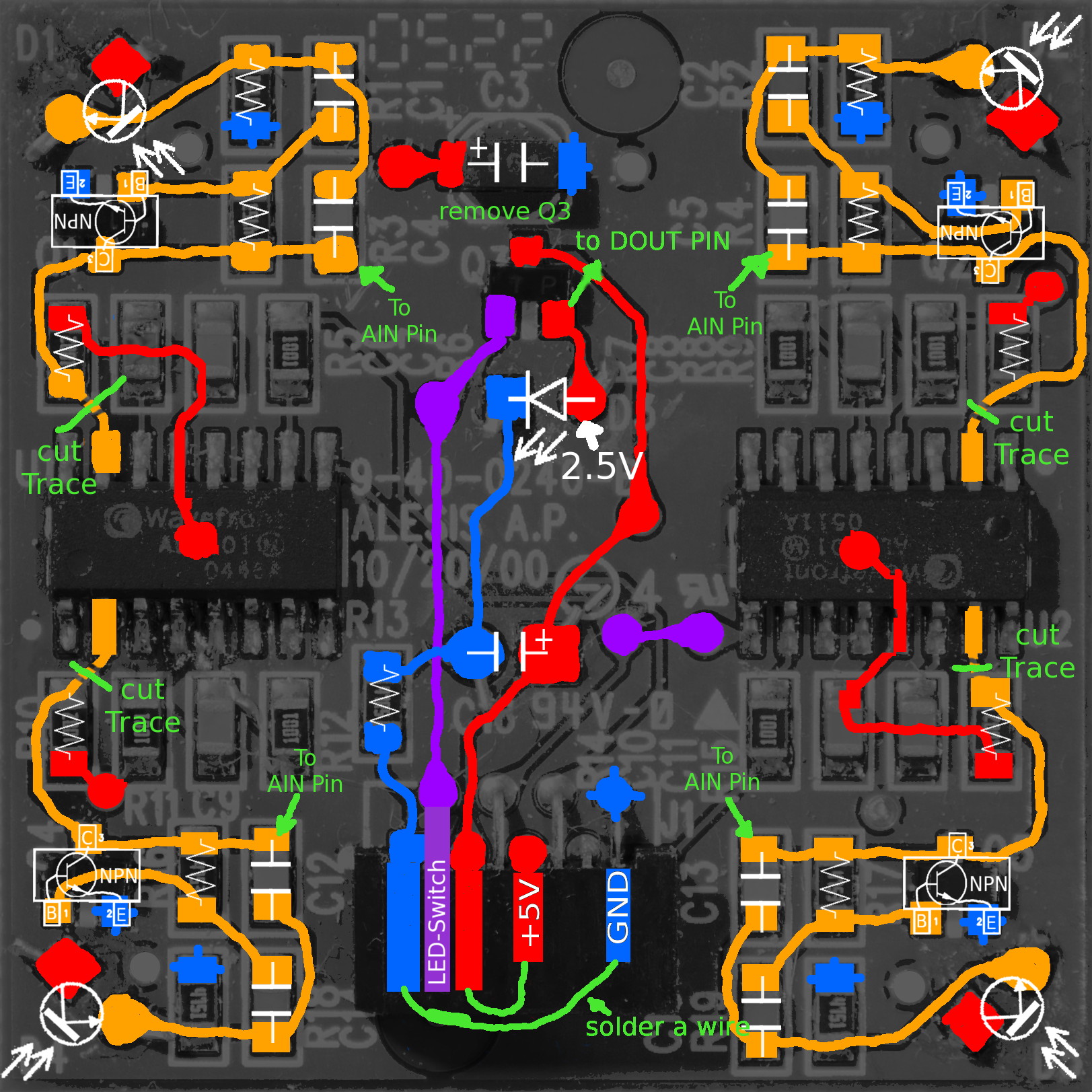
ok, the LED gets 4,6VDC on its Circuit and 2,5VDC direct on the LED... it is Switched by DOUT, (so it only Lights when the XYZ Dome is activeted on the UI)
maybe they switch the LEDs on of frequently, to find out what is ambient infrared Radiation in the room, and make some software offset... i dont know
-
hey.
i started a wiki:
http://wiki.midibox.org/doku.php?id=xyz-ir-controller
its the last peace of my Photon X25 Midification... it could be the hardest part...
the Controller uses one IR-LED as Sender, and 4 IR Transistors to receive the Axis (while Z-Axis is some Delta of all 4 Transistors)
I painted all Traces on the PCB, and the Circuit is pretty Simple:

...
the datasheet of the ICs says that the uses a 24Bit Audio Stereo ADC from Alesis which runs on Wordclock.... (still aviable for 2,9dollars...)
http://wiki.midibox.org/lib/exe/fetch.php?media=phatline:al1101-datasheet.pdf
i defintivly have no glue how or if there is a way to interface that to the Midiboxworld...,
...maybe i will end up by removeing the ADCs, and go directly in J5A of Core32F4...
but maybe i understand something completely wrong... it could be that the LED send some Signal (not just ON all the time), maybe its necessery, maybe not...
how ever, i ask you for help, or your thougts. - mike
-
hi
i used J5 for LED Indication, and one User-Button, see this: MSQ-CC-BCR
i used this code for Initialisation:
void APP_Init(void){

  // LED:  initialize J5A pin1-3 & J5B pin0-3 as outputs in Push-Pull Mode
  int pin;
  for(pin=1; pin<8; ++pin) {MIOS32_BOARD_J5_PinInit(pin, MIOS32_BOARD_PIN_MODE_OUTPUT_PP);}
     int a; for(a=1; a<8; a++) { MIOS32_BOARD_J5_PinSet(a, 0);} //Turn off all LEDs

  // MOMENTARY-BUTTON   initialize pin 0 of J5A,  as Digital input with internal Pull-Up
    MIOS32_BOARD_J5_PinInit(0, MIOS32_BOARD_PIN_MODE_INPUT_PU);
}
as exemple - in app background, for reading the J5 States:
void APP_Background(void){    // Set Bet Structure without LCD but with PIN 1 of J5A

	static rythm = 0; // initalized once
    // check J5 pin 0 for changes
    static s16 count       = 0;

    if ( MIOS32_BOARD_J5_PinGet(0) == 0 ) { count = 500; }
    if ( count != 0  ) { count--; }
    if ( count == 1 )  {

                rythm_count++; // count thru

                switch ( rythm_count ) {
                        case 1:  rythm = 3;  break;
                        case 2:  rythm = 4;  break;
                        case 3:  rythm = 5;  break;
                        case 4:  rythm = 6;  break;
                        case 5:  rythm = 7;  break;
                        case 6:  rythm = 9;  break;
                        case 7:  rythm = 11; break;
                        default: rythm = 13; break;
                        }
      }
}
if you want to Activate a J5 with the variable rythm_count from above (switch thru the LEDs), put it also in APP_Background for example
                    for( x=1; x<8; x++) { MIOS32_BOARD_J5_PinSet(x, 0);}   // Turn off all LEDs

                    switch ( rythm ) {
                        case 3:  MIOS32_BOARD_J5_PinSet(1, 1); break; // Turn on one LED - Indicate rythmset
                        case 4:  MIOS32_BOARD_J5_PinSet(2, 1); break;
                        case 5:  MIOS32_BOARD_J5_PinSet(3, 1); break;
                        case 7:  MIOS32_BOARD_J5_PinSet(4, 1); break;
                        case 9:  MIOS32_BOARD_J5_PinSet(5, 1); break;
                        case 11: MIOS32_BOARD_J5_PinSet(6, 1); break;
                        case 13: MIOS32_BOARD_J5_PinSet(7, 1); break;} break;
i am still unsure what you mean with USER-Button, if you mean one of the onboard buttons, i cant help you... stil i dont see a need to use them to initalize the J5 GPIO... i would do this in APP_Init hardcodet, or with a other DIN... however thats it from my side.
-
where in the program did you put the "pin changed" code? i am pretty sure that you have to initalize the pins in the app-init, as a Digital input before..
if you have time till the day after tomorrow, i am not at home right now...
-
THX that solved it!
-
or could J19 (SPI2) reused, for a second "J8/J9" like SR "Chain"? (has this already some one done, which app?)
J16 cant be used because of:
QuoteJ16 is normaly connected to a SD Card
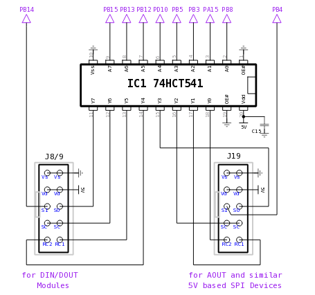 Quote
QuoteJ19 doesn't support DMA transfers, so that MIOS32_SPI_TransferBlock() will consume CPU time (but the callback handling does work).
so maybe not...
&&
QuoteMIOS32_spi.c says:
//! J19 provides SPI + two RCLK lines at 5V.
//! It's some kind of general purpose SPI, and used to communicate with
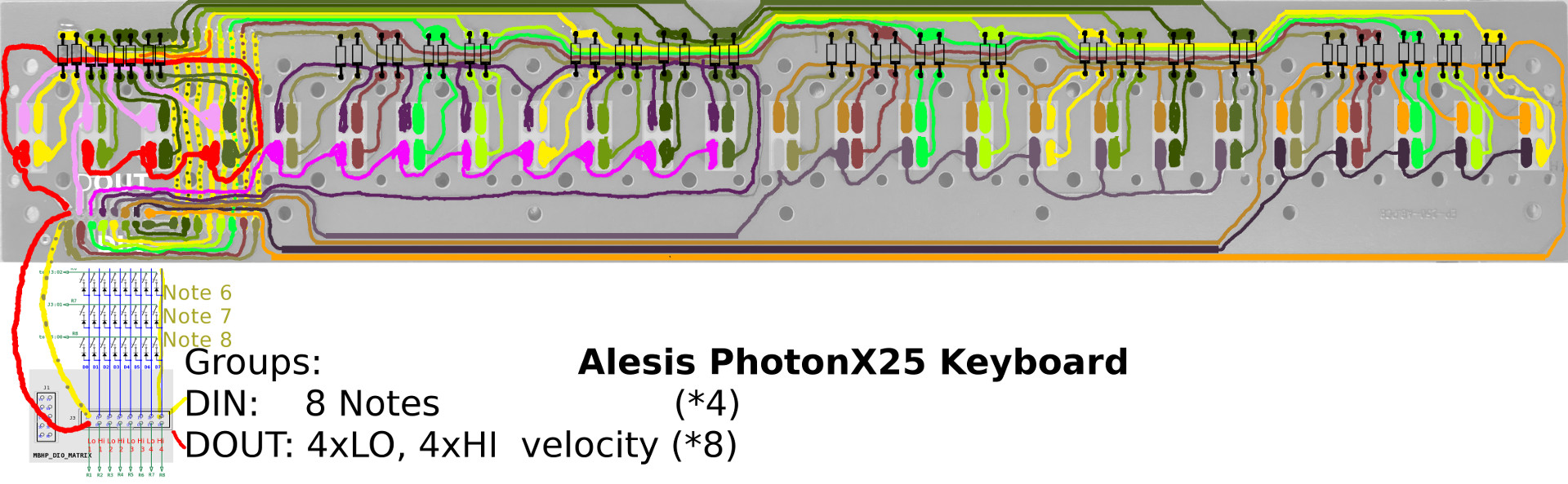
//! various MBHP modules, such as MBHP_AOUT* and MBHP_AINSER*....By the way this is the Keyboard Layout...:
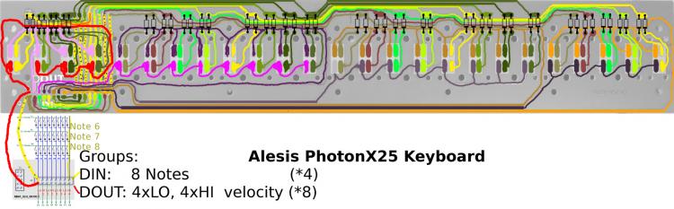
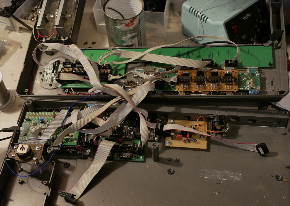
and thats the midibox stuff... its getting pretty full in there ;)

-
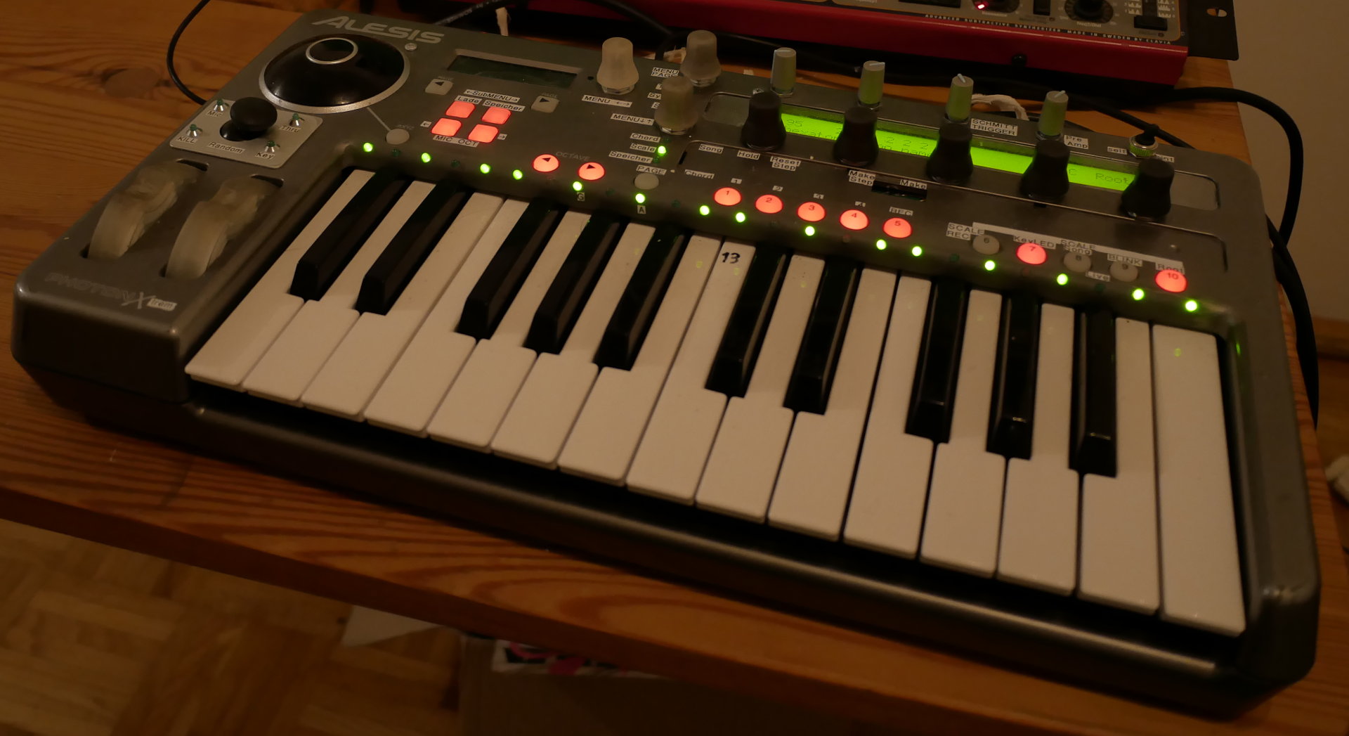
i have a small 25keys keyboard here (alesis proton x25), i managed to get the keys velocity sensitive to working, the connector is 1:1 to the DIO-Matrix ---lucky me!
but i run into the problem that the code uses:
#define MIOS32_DONT_SERVICE_SRIO_SCAN 1
which disables my normal Shiftregisters for Encoder I cant use the J10 or J5 for it, because they have to less pins, and they are already used for other stuff anyway...
How can i use the Shiftregistors? ... i have 4 DIN and 4 DOUT Registor in addition to the MB-DIO-Matrix
I read that in for example the MB-KB code:
/////////////////////////////////////////////////////////////////////////////
// This hook is called after the shift register chain has been scanned
/////////////////////////////////////////////////////////////////////////////
void APP_SRIO_ServiceFinish(void)
{
  // -> keyboard handler
  KEYBOARD_SRIO_ServiceFinish();

  // standard SRIO scan has been disabled in programming_models/traditional/main.c via MIOS32_DONT_SERVICE_SRIO_SCAN in mios32_config.h
  // start the scan here - and retrigger it whenever it's finished
  APP_SRIO_ServicePrepare();
  MIOS32_SRIO_ScanStart(APP_SRIO_ServiceFinish);
}
i dont know what that mean? should it still working then?
i found out, that i still can activate LEDs, and i get the DIN-States, however i dont get any ENC Values
The Hardware itself is functional since i debugged it with tutorials/015_enc_absolute
i am pretty sure that something in here, break the enc routine:
void APP_SRIO_ServicePrepare(void){

	  // select next column, wrap at 16
  if( ++selected_row >= MATRIX_NUM_ROWS ) {
    selected_row = 0;

    // increment timestamp for velocity delay measurements
    ++timestamp;
  }

  // selection pattern (active selection is 0, all other outputs 1)
  u16 selection_mask = ~(1 << (u16)selected_row);

  // transfer to DOUTs
#if MATRIX_DOUT_SR1
  MIOS32_DOUT_SRSet(MATRIX_DOUT_SR1-1, (selection_mask >> 0) & 0xff);
#endif
#if MATRIX_DOUT_SR2
  MIOS32_DOUT_SRSet(MATRIX_DOUT_SR2-1, (selection_mask >> 8) & 0xff);
#endif}

}


void APP_SRIO_ServiceFinish(void) {
  // check DINs
#if MATRIX_DIN_SR
  // the DIN scan was done with previous row selection, not the current one:
  int prev_row = selected_row ? (selected_row - 1) : (MATRIX_NUM_ROWS - 1);

  u8 sr = MATRIX_DIN_SR;
  MIOS32_DIN_SRChangedGetAndClear(sr-1, 0xff); // ensure that change won't be propagated to normal DIN handler
  u8 sr_value = MIOS32_DIN_SRGet(sr-1);

  // determine pin changes
  u8 changed = sr_value ^ din_value[prev_row];

  if( changed ) {
    // add them to existing notifications
    din_value_changed[prev_row] |= changed;

    // store new value
    din_value[prev_row] = sr_value;

    // store timestamp for changed pin on 1->0 transition
    u8 sr_pin;
    u8 mask = 0x01;
    for(sr_pin=0; sr_pin<8; ++sr_pin, mask <<= 1) {
      if( (changed & mask) && !(sr_value & mask) ) {
	din_activated_timestamp[prev_row*8 + sr_pin] = timestamp;
      }
    }
  }

#endif

  // standard SRIO scan has been disabled in programming_models/traditional/main.c via MIOS32_DONT_SERVICE_SRIO_SCAN in mios32_config.h
  // start the scan here - and retrigger it whenever it's finished
  APP_SRIO_ServicePrepare();
  MIOS32_SRIO_ScanStart(APP_SRIO_ServiceFinish);
}
-
i do have my own code for it, and did already pinout via gpio on a other project... now i have mixed lcd types... and the question was which typ i have to choose on the bootloader app for mixed types?
LM1117 variable Voltage Regulator - timelapse built
in Songs & Sounds
Posted · Edited by Phatline
I made this Voltage Regulator to have a variable Voltage from 1,25 to 12V.... music is from my tekkno-project "GreatFullTekk", i have different names for different genres and bands i am involved...(phatline, crimic, greatfulltekk, mjsigl, mms...)
i always take own music creations for my videos... lukkely i have hundrets of it ;)
i use it to drive a Hi-Voltage Generator - to field some plant seeds ( a expirment which i really want to check if there is anything true on it! - dont belivie it until you confirmed it ;) ) - music by Crimic