

Karg
-
Posts
60 -
Joined
-
Last visited
-
Days Won
3
Content Type
Profiles
Forums
Blogs
Gallery
Everything posted by Karg
-
Works like a charm now! Still annoys me, that mistake :) Particularly since it is mentioned everywhere to check the parts number (and I actually confirm every single item). I guess mistakes happen. Thanks a lot again for the quick and competent help!!! A beer is coming your way :) Actually, you don't happen to live in the Rhein-Main Area in Germany? Then we could have that one in person...
-
Aaaaah, this could have been so obvious. I will see that I change the ICs and then report back. Thanks a lot already!!!
-
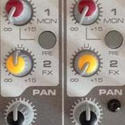
Wow, thanks for the prompt response!!! RN pin 16 showes 5V. So does pin 1 and 16 of the 165. However, none of pins 3-6, 10, 11-14 is on 5V! 165 pin 7-8 have a resistance of 5MOhm (not sure if thats"normal), the rest is not shorted at all. The RN has the writings 4816P LF 1-103 C184 on top. No pins seem connected using a multimeter. Pictures are following. Actually, alone. That explains the matrix well. I was wondering already since the pins of the shift registers don't relly match up to the number of LEDs. Thought some fancy multiplexing is used :)
-
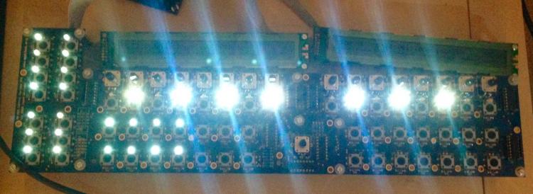
Hey guys, after succesfully building two Seq V4, I could not resist the V4+ version. In this context, I just populated the JA PCB, however, it unfortunately is not working as expected. My problem is the following: Using the NG application with SEQ_L.NG, I can trigger all LEDs individually by sending NoteOn commands from MIOS Studio. Yet, pressing any switch causes an irradic behaviour with several NoteOn being send (Ch3) and consequently several LEDs lighting up. Similarly, touching any solder point by hand elicits a similar random NoteOn and flickering response. Touching the SrOut connector fires multiple NotOn on Midi Ch1. Furthermore, sending CC16 from MIOS Studio does not light any led on the 16x8 matrix . In fact, during all my tests, I have not seen any of them lit :( Naturally my first suspect for the multiple NotOn messages were the 100n cap of the 74HC165, the IC itself, or the resistor network. I do not know how often I have checked and/or re-done the corresponding solder joint. Nothing has helped so far. I further checked the orientation of the 165 and the resistor network, as well as their part number based on the mouser BOM. For the 16x8 matrix, my tests were rather limited. I could not do a diode check before soldering, but the letters on the matrix side point to the bottom, and the parts are from Midiphy. Since I am currently running out of ideas, any help would be appreciated.
-
[success] Project: MidiBox SEQ V4 with Standalone LaunchPad Pro as BLM
Karg replied to sylwester's topic in MIDIbox SEQ
@FlavioB: Operation is more or less the same as all other BLMs, so most likely, you will not need a "manual". However, I started writing my own BLM for the Launchpad Pro some weeks ago. While it is not finished yet, I can give you a recent version if you give me feedback in return :) Just PM me if you are interested... -
Same here :)
-
[success] Project: MidiBox SEQ V4 with Standalone LaunchPad Pro as BLM
Karg replied to sylwester's topic in MIDIbox SEQ
Great work! I am very eager to try this as well! By any chance, in case you have updated your Launchpad code, could you make that available as well? Will be happy to give you feedback of course! -
No worries, this is a hobby for most of us and everybody understands your situation. However, I also can offer my help. I have all the parts required - except the CS. Desperately trying to get it...
-
I am still struggling to get my OLEDs to work properly. Giving themtheir own power converter did not significantly change anything. The solution to lower the supply voltage only made it worse by making the displays flicker. I then requested the datasheet of the OLEDs and when I got it (file attached), it seems the problem is the opposite: the data pins need to be supplied with 5V and will not work with 3.3V. Thus, I am getting a SN74LVC245, to try converting them to 5V now... 56-2586_v1.pdf
-
The sentence that concerns me a bit in the description is "The UBEC has built in filter capacitors on the input and output, but its a switching supply so its a little noisy compared to a linear regulator." It sounds as if I reach the same result with just adding filter capacitors to the switched power rail I already have. However, in my initial try that did not work, but maybe I should use different capacities. I think I will do some tests over the weekend using the 12V line with an 7805, just to see if that solves the problem and how hot it gets. I still would prefer to use the 5V rail I already have installed so I guess I will also try different capacitors for filtering. Would something like this maybe also work: http://www.hobbytronics.co.uk/s7v7f5-5v-regulator ?
-
I have the very same problem as jbdiver. Winstar white OLED set to 5V, only nonsense characters get displayed. I understand that stabilising the supply rails will solve the problem, hence I have tried a 1000µF bypass capacitor (had this size lying around) but without success. My SeqV4 is already powered by an external supply that provides 5V (to the STM32F4) and 12V (to the AOUT board) so I can easily use these for the OLEDs as well. Is there a good way to harness the 5V line from the ext power supply and somehow stabilize it? I would like to avoid using a regulator on the 12V and dissipate the difference in heat. Similarly, I would like to avoid adding another supply voltage. What would you guys recommend? Any help is greatly appreciated!
-
Hello all, I am looking for the PCB for Wilba's front panel. Unfortunately, it is sold out in SmashTV's shop since summer already. Hence my questions: (1) Does anyone have a spare one I could buy? or (2) If other people are interested in getting one, and I somehow get the Gerber files, should I organise a group buy and have some produced? I am located in Germany :) Best wishes and a great start into the new year, Karg
-
@Lamouette: Thanks a lot. worked well. Actually it did not, but it was exactly what I needed - a hint in which file the IIC ports are configured (and the hacked PIC16 Firmware of course was very valuable as well). For completion: the line to change in mios32_config.h is #define MIOS32_IIC_MIDI_NUM 8 Besides solving my problem, I now also have the mios toolchain installed and can try a couple of different things! This is what I love about DIY!
-
Hello, I seem to not find the information on how to enable a second Quad_IIc MIDI module for my SEQ V4 with STM32F4 core. Could someone please point me towards the right direction? Any help appreciated :) Thanks, Karg
-
@tashikoma: Thanks, I'll give it a try :)
-
Hi Latigid On, thanks for the quick reply, but I don't understand what you want to tell me with it. Maybe I should explain my problem in more detail. I have a Pickit3 and use the MPLAB IPE software. I connected: PICKIT_PIN1-16F88_PIN4 PICKIT_PIN2-16F88_PIN14 PICKIT_PIN3-16F88_PIN5 PICKIT_PIN4-16F88-PIN13 PICKIT_PIN5-16F88_PIN12 In the IPE, I select "Power from Tool" (or something like that) in advanced options. I also tried puting a variety of caps and resistors around the PIC as found on the web. However, I always get "Target Device ID (0x0) does not match expected Device ID (0x70)" as an error message...
-
Hey Tashikome, by now, I also got a Pickit 3, however, when burning the PIC16F88, I go from error message to error message. My suspicion is that is has something to do with the wiring of the PIC. Could you (or anyone else) please post how you have wired yours? Thanks a lot!
-
I just confirmed the orientation again, all correct.
-
I am using firmware midibox_seq_v4_090b, which according to the changelog supports the Wilba. Is that correct?
-
Hey all, I experience a problem while assembling my Wilba front panel pcbs for the Seq. While everything worked fine (I had left out the LEDs first), last night I soldered the LEDs and something is wrong with my multiplexing. Among the step LEDs, every even step LED (2, 4, 6, etc) is always on and much brighter that it should be according to the used resistor. Also all LEDs on the left hand side of the board are always one, but much dimmer that they should be. Since I discovered this while testing during the assembly, I stopped and did not solder the LEDs above the start/stop/etc buttons, so I cannot comment on them yet. Visual inspection of the PCB and its solder points look good. I also reheated all LED solder points by know and carefully checked for bridges among them. As a configuration file, I use the standard file that is suggested for the Wilba panel. Any help indicating me into a direction where to best investigate is appreciated. Thanks a lot in advance! Best, Karg
-
TK. and I agreed that I'll send him my problematic card for analysis. However, in the process, I moved flats and all my DIY stuff had to rest for a moment. I am getting back on track now, but have not found the SD card yet (of course I packed it in a "special" place so that I can directly bring it to the post office). Sorry for the delay from my side...
-
Thanks for the answers! :) Since the PICkit 3 (I guess it is this one: http://www.microchipdirect.com/ProductSearch.aspx?Keywords=PG164130) is only 9 Euro more than a clone of the PICkit 2, I guess I will go for the first one. @Rowan: You need to use it with some kind of adapter, right?
-
@jjonas: thanks for pointing it out, he describes the very same problem! @tk: sure, no problem. Just drop me a pm where to ship it too...
-
Yes, that was the first thing I did. Even took an SD image from a working (although very slow) card and mirrored it on the Transcend, no change. However, what I figured by now, the new card works well if I boot the Midibox without a card, and then only insert it when it is running already. Any other card I use does not cause similar problems. However, since all my other cards at home are class 4 only, there is a significant interruption each time the card is accessed :( That is why I was asking for the experience of people. You say Kingston works well? Can you point me to a specific model? What is the experience of others?

