Search the Community
Showing results for tags 'led'.
Found 7 results
-
hey guys, i am planning on getting some midibox pcbs done, mostly cause i need them myself but i might just do a slightly bigger run and make them available to the community at cost. mostly i am looking to do a version of @Fairlightiii's rotary encoder / led ring board: http://www.midibox.org/dokuwiki/doku.php?id=mb-lre8x2cs_rev4.6 4x2 encoders seems fine, as discussed here but i really want to do a 4x1 version instead, to keep it more modular for different configurations. now here's the thing. by now i got back into electronics enough that i can (barely) assemble the simpler ones of my diy kits. yeah i understand a resistor. but designing/altering a circuit would eat up way too much time for me. so here's my request: is there anybody anybody willing and able ont his board to help me change/reconstruct a proper 4x1 midibox-compliant pcb circuit based on this info? http://www.midibox.org/dokuwiki/doku.php?id=mb-lre8x2cs_rev4.6 i am also thinking about getting the CORE and DIN/DOUT modules done, especially for easier EU availability. but those are somewhat available through modular addict so i am talking to him too to see what makes sense. based on the first cost estimeate i got from china i think i might want to produce the ENC/LED modules FULLY ASSEMBLED, with smd leds and all circuitry, but without the encoders. also in the end i will try to have them done in china and work with local EU producers instead, depending on the financial overhead of that. once i have the circuit design settled i will msot likey also start a bulk buy thing here.
-
Hi, in the pdf on the Wilba frontpanel button/LED matrix, the dual-color GPx LEDs are said to be hardcoded into the firmware. But in the said pdf the information on how to wire them is confusing. In the schematic the dual-color LEDs are wired to pins D4-D7, but in the chart next to the schematic they are wired to pins D3-D0. The question is: which version in the linked pdf – schematic or chart – is the one that I should use if I want to make a DIY frontpanel with DIO matrix?
-
Hey all, I experience a problem while assembling my Wilba front panel pcbs for the Seq. While everything worked fine (I had left out the LEDs first), last night I soldered the LEDs and something is wrong with my multiplexing. Among the step LEDs, every even step LED (2, 4, 6, etc) is always on and much brighter that it should be according to the used resistor. Also all LEDs on the left hand side of the board are always one, but much dimmer that they should be. Since I discovered this while testing during the assembly, I stopped and did not solder the LEDs above the start/stop/etc buttons, so I cannot comment on them yet. Visual inspection of the PCB and its solder points look good. I also reheated all LED solder points by know and carefully checked for bridges among them. As a configuration file, I use the standard file that is suggested for the Wilba panel. Any help indicating me into a direction where to best investigate is appreciated. Thanks a lot in advance! Best, Karg
-
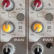
Hey guys I evaluated an LED backlit push button switch for my Synth project. Well Buying's TC011-A S4 T turned out to be the perfect switch for my needs: Although called tact switch, it feels more like a push button switch with a smooth pressure point and doesn't have the distinct click of a membrane switch. It's more like a Marquart but with a stronger spring resistance and a more defined switching point. The cap is 11x11 mm, translucent with a white diffusor cap inside (other versions with only square white caps are also available), as well as an ergonomic indent. There are different color options as well as duocolor and RGB available. Unfortunately, the duocolor version (colors can be chosen freely, as far as I know) is a bidirectional setup, where the LED has to be adressed by switching the polarity of the two leads. The switches can be obtained relatively cheap directly from the manufacturer Wellbuying from China. For a lot of 100 pcs, I paid only USD 0.78 a piece for a single color version. If anybody is interested, I can post pictures of the yellow as well as the orange version in action. I also have a contact, if somebody needs switches. Meanwhile, they are also available through Mouser, but for a much higher price. Find an individually addressable four button PCB eagle schematic for single LED type TC011s including the part library: LEDSwitch_Matrix_0.7_4.brd LEDSwitch_Matrix_0.7_4.lbr LEDSwitch_Matrix_0.7_4.sch Important: In case you want to use these PCBs in conjunction with a Schaeffer frontpanel with standoffs (no through hole), the mounting holes on the PCB need to be further apart as the glued on standoffs have quite a large base which otherwise interfer with the routed holes for the buttons.
-
My freshly finished MB Seq V4 with Wilba's standard CS is working nicely except that a few LED's are constantly lit. Affected LED's are: Track Group 3 Track 2 Track 4 Trigger Layer B Parameter Layer B Step View (fully lit) Solo They are all a bit dimmed (except Step View) and they become fully lit when their button is activated. There is 2.27V going through these dimmed but lit LED's. I can't see any bad solder joints. The only clue I've come to is that all affected LED's are assigned to pin 1 of various SR's (shift registers?). Other normally working LED's are using different pins. I have no idea if this can be related somehow. Here is the excerpt from the config file. ################################################## # LED assignments to DOUT pins # SR = 0: LED disabled # SR = 1..23: directly forwarded to DOUT pin # SR = M1..M8: forwarded to a 8x8 LED matrix ################################################## # SR Pin LED_TRACK1 M7 2 LED_TRACK2 M7 1 LED_TRACK3 M5 2 LED_TRACK4 M5 1 # SR Pin LED_PAR_LAYER_A M4 2 LED_PAR_LAYER_B M4 1 LED_PAR_LAYER_C M4 0 # SR Pin LED_BEAT M1 1 # SR Pin LED_MIDI_IN_COMBINED 0 0 LED_MIDI_OUT_COMBINED 0 0 # SR Pin LED_EDIT M5 3 LED_MUTE M6 3 LED_PATTERN M6 2 LED_SONG M7 3 # SR Pin LED_SOLO M6 1 LED_FAST M6 0 LED_FAST2 0 0 LED_ALL M7 0 # SR Pin LED_GROUP1 M8 3 LED_GROUP2 M8 2 LED_GROUP3 M8 1 LED_GROUP4 M8 0 # SR Pin LED_TRG_LAYER_A M2 2 LED_TRG_LAYER_B M2 1 LED_TRG_LAYER_C M2 0 # SR Pin LED_PLAY M1 3 LED_STOP M3 3 LED_PAUSE M2 3 LED_REW M3 2 LED_FWD M1 2 LED_LOOP 0 0 LED_FOLLOW 0 0 # SR Pin LED_EXIT 0 0 LED_SELECT 0 0 LED_MENU 0 0 LED_BOOKMARK 0 0 LED_SCRUB 0 0 LED_METRONOME 0 0 LED_RECORD 0 0 LED_LIVE 0 0 LED_UTILITY 0 0 LED_COPY 0 0 LED_PASTE 0 0 LED_CLEAR 0 0 LED_UNDO 0 0 # SR Pin LED_STEP_VIEW M3 1 LED_PAR_LAYER_SEL 0 0 LED_TRG_LAYER_SEL 0 0 LED_TRACK_SEL 0 0 Any tips or suggestions are welcome. Thanks!
-
Today I etched a few more PCBs. Now the control surface is complete. Or that is - I haven't yet soldered on most of the cables on the new boards, but components are soldered, backlight on the menu encoder is tested, ok (looks good as expected hehe) and I laid it out on the workbench to see how I want the frontpanel to be. I think I'm gonna use this setup here, unless I get any bright ideas or any bright tips :). It has 8 general purpose encoders, 8 general purpose buttons, encoder for left/right navigation, it got the enter button (besides the menu encoder, and it got the snapshot button by itself - on the same pcb as the enter button :). The buttons is just the same as in the mb6582. I have looked around the net (especially on ALBS) and found many very cool tactile switches that I could easily used for this box, but the reason why I used these buttons is that I had them in my drawer NOW, and I had a lot of em, so I figured - simple and fast - no waiting for parts etc etc. so that's why the buttons are rather boring - but I suspect they'll do the job anyway hehe. In addition - its gonna have 4 analog inputs on the back (via mini-xlr) - for expression pedals mmmmmmmmmmmmmmm. Since I have only one pedal now, I have to have a way to ground the unsused input easily without opening the case - so I have ordered in a bunch of dip-switches. I have thought and thought, and I think this is a cool solution - dips available from the back panel. Makes it easy to "program" when I need it, and hard to accidentally operate :). It got the 16x2 LED - wich has green letters on black background, and green backlight for knobs. Any day now, the Core8, AIN, DIN and a bunch of other goodies are dropping in my mailbox from smashTV, and once I get those, I can wire everything up and actually test it. If everything works in a satisfying way, I'm building the case next - I'm doing it simple - just bending some alu plates and put together. Give it a coat and 10 of cool paint, and we're there. If I come across a case I can use, I'll do that instead of making my own - wich takes long time even if it's simple design. Well, enough talking, lets see the picture :). - yes there is only one today :P.
-
Yo! Just thought I'd do a small blog entry on the sideproject (I consider the synths my main projects). A midibox 64e. This is a short term project, and all parts have arrived or are on their way. It's gonna have 9 encoders, lcd and some buttons + 4 expression pedal connections. One pedal is soon built - waiting for the last parts to arrive from the states :). Anyway, some of you might have seen my picture of the encoder PCB. Now, here is a couple of pics of the finished built pcb. Also fitted on top is a PCB mockup (thick paper). This is gonna be housing all the smd leds for the knob backlights. This hasn't been etched yet because I discovered I needed to do a couple of layout changes - the leds are a bit too close to the encoder shaft than I'd like it to be... :). As you can see, this is gonna be a encoder control surface sandwitch :D. The cables are rainbow ribbon cable from tim's and I have split them up and put on some nylon stockings :P. Heat shrink tubes holds them in place ;).