

ChinMuzik
-
Posts
105 -
Joined
-
Last visited
-
Days Won
1
Content Type
Profiles
Forums
Blogs
Gallery
Everything posted by ChinMuzik
-
All the diodes polarity are correct. The LCD no longer freezes when selecting patches. Not sure what resolved that issue. The buttons for Filter, CC, Sync, SID 1 and SID 3 do not work. Is there a way to test tactile switches with a meter? Even though I highly doubt 5 switches would be bad.
-
Ok I am an idiot.... I never installed the pin headers for J09 which supplies the 5v for the encoders. Now they all work fine. But I am still clueless as to what is making the buttons and LED matrix behave so badly.
-
So they are the proper resistor networks. and the orientation is good. I am really at a loss now. i went over the cs and base board traces to see anything broken but all looks fine.
-
I've checked all shift registers and swapped them with new ones. Checked orientation twice. Reflowed each socket and checked continuity on each socket pin. ibthen checked continuity on each pin on the cables connecting the base and CS which was fine. Also, the resistor networks have proper orientation...however I did not populate this board sobI do not know if these are the type that have common pin 1. How would I discern? I'm still getting nothing from the encoders and some buttons do not work...SId 2 and 4 work but not SID button 1 and 3..
-
.5A is not going to do it. The original c128 PSU's are decent and have better lifespan than the c64 ones which are ticking timebombs. I had one built by Ray Carlsen...pricey but worth it. they are well built switching supplies, noise free with built in protection and the 9v side provides 1A and I believe 2.5A on the 12v (I used a mixed SID setup).
-
Thanks, Synthy
-
Has anybody used these? Says they are standard hd44780 but the website has been down for weeks (even since last year when I browsed) and when I received the LCD it came without the datasheet. The seller never responds. Terrible communication. I even sent the message translated to Polish and no response.
-
I will buy 50 I'm also in NA
-
Regular SIL and DIL headers. 2.54mm pitch
-
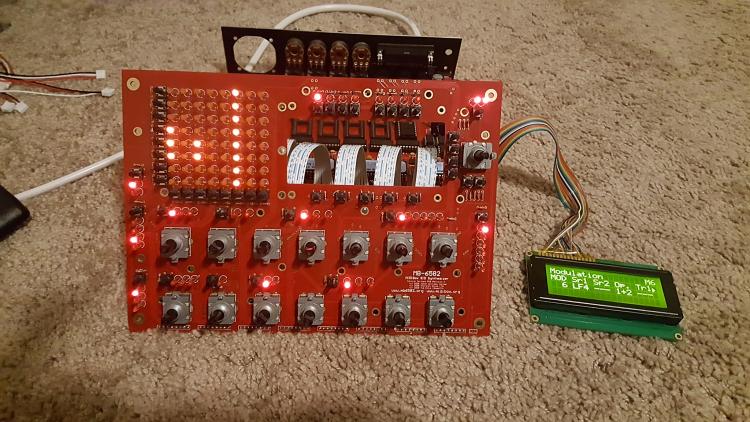
I just completed the construction for the CS of my MB-6582 build. I succesfully installed MIOS and the LCD is working as it should. After installing the current limiting resistors...when powering on the unit..I get a strange pattern on the matrix. Column 6 of the matrix flashes steady and no matter what I do it won't stop. Also, a couple of the controls LED's pulse very dimly in the same pattern as the matrix column. Several buttons do not work. There is also no response from any of the encoders. And another strange thing, the LCD will freeze and time a "poly" patch is selected. EDIT: I noticed the LCD freezes only when browsing patches while the matrix is in MATRIX mode...if in METER mode it browses fine. I checked soldering and no bridges and no visible shorts. I reaseated the shift registers and checked 5v supply on all sockets which is good. Cleaned all residue on the bottom of the board. After reseating, now some buttons behave strangely (along with ones that didn't work before)
-
Hi, Mike took care of me. Thanks for the reply!
-
Anybody? I emailed Mike and have not heard back.
-
MB-6582 board set availability (possible bulk order?)
ChinMuzik replied to urtzurd's topic in MIDIbox SID
Looks to be the end of a good thing... I'm guessing the best hope is for someone new to create their own edits. I wouldn't hold my breath waiting for smashtv to have another run. -
It's a 5vdc/9vac psu It's hacked together from two different wallwarts to a single 7-pin DIN as my original c64 psu died.
-
The scope is showing a straight line on all rails. Even the 5v rail I cannot see a waveform, however, I test the 5v rail and all the sockets with a multimeter and it is supplying the 5v. I'm testing from the test point pin headers. I tested the 9v and 5v pins on the power supply and took screenshots of those.
-
I am currently trying to upload the MIOS app to preflashed PIC and for some reason the core is not communicating. I did the MIDI loopback and communication workup and everything is ok. So I checked the PIC socket for 5v and they are receiving 5v fine on necessary pons and GRD os ok too. But I noticed when checking voltages that the 9v and 12v pins do not receive proper voltage. 5v is consistent but 12v will show .45 and 9v about 4.5v most of the time....very rarely will I see full 9v and 12v on the pins (or SID socket) What could this be? Is this possible a bad PS?
-
DCO, They (x0xb0x) sell the board for $20...if you are getting the board fabbed you will be paying more than that unless you plan on getting 100 of them fabbed.
-
Does anybody have another one? Or maybe the rendering for ponoko so I could order one maybe?
-
Has anybody got a 4x20 OLED working in their mb6582 with a step-by-step? I was directed to this thread but seems there is no final conclusion?
-
So in each core, if there's a stereo pair..a single patch can be played with 6 voice polyphony? And With an 8 SID configuration I can have 24 voice polyphony if I split the keyboard between the 4 engines on different midi channels?
-
I've decided to go and gut one of my breadbins to house a SID v2, hopefully using a stereo pair of 6581 and 8580. Maybe I can learn while I wait in hopes of the MB6852 boards, or learn enough and fab my own board solution. One thing I am confused a bit over...is the photo gallery of TK's c64 SID build. It shows a complete control panel but I don't see where the DINX4 and DOUTX4 modules are located. I see the CORE, MIDI and SID modules. I'm just trying to get a feel if I will be able to stuff all the modules in the case.
-
MB-6582 board set availability (possible bulk order?)
ChinMuzik replied to urtzurd's topic in MIDIbox SID
I will buy 2 or 3 sets of boards. -
Does the SSU have a sine wave? I don't recall if the original swinSIDs do. I'd love a sine wave in a SID build.
-
Updated... Just seeking mb6582 CS board
-
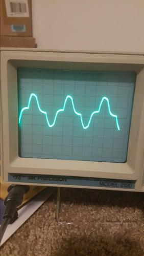
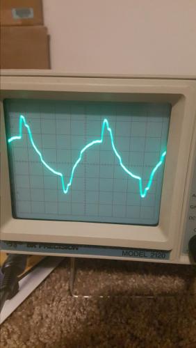
You've tested a SwinSID ultimate? I was aware of the lower output on the original Swin, and I did notice the waveform comparisons for the ultimate are indeed lower output than the original.. but enough to be a dealbreaker?


