Noise-Generator
-
Posts
193 -
Joined
-
Last visited
-
Days Won
18
Content Type
Profiles
Forums
Blogs
Gallery
Everything posted by Noise-Generator
-
 Well, would be better he also paid the shipping if he sells broken psus, but maybe you can get some bucks for the broken one. May you also have seen that there is a polish company selling new c64 psus on ebay (maybe not in usa), but those are really expensive. It's unusal that they deliever less volts than 5, normally, if the 5v rail is broken (regulator), it delievers more than that and kills everything inside the c64 what needs just 5v. (rip sid) Thats why c64 users today building "crowbar" protection stuff inside their psus and the community is still fighting each others solutions. As far as I read the last times... For a c64, a combination of a 9vac and 5v psu is an alternative and usual but I don't want to contradict latigid on, in case of a midibox you generate 20v ac by a magic act of mixing dc and ac, therefore this solution is profen exclusively at this psus. I do have some c64 psus but try not to use them. They may have the best noise ratio, Thorsten wrote, but I want to use a Laptop psu with a 12v and usb 5v rail, it's smaller and you get them for 17€. I can't recommend them at this point, I still did not tested em in mixed mode but 12 for the sid and 5v for the core, works (yeah, why shouldn't...). The question is still what happens by using the 12v for the old sid and transform this rail to 9 for the new sid.
 -
That's not normal, a C64 PSU has 5.20V.
-
Hell yeah, me too ;) But next time you read someone, having the same issue, your first question will be…have you uploaded mios? It's better to upload first than to try uploading other stuff, uncessfully... I can't say if it's written where you have looked, I can't find either a wilba documentation or a sammich. You need to understand that these are one pcb designs which did come later and are based on the modular designs of multiple components and the creators may think, it's logic, you just need to look at the pages which handle the topic. I red it on the core page, setting up the core, mios8 and there are readmes. Have fun with your Sammich
-
I'm just sceptic because you did need to install a special driver instead of a default. I'm used to have plugnplay with midi interfaces. Mios Studio worked good with my Win 10 but I don't like it and now my Windows machine has 7, and yeah, in case of old audio interfaces it's also the better choice. Btw, there is a rumor that if you update your win7 to win10 (by a previous installed 7 and the drivers you need) the possibility is given that those drivers still work under 10 but not if you install them in 10, just if you upgrade.
-
You can read about the "Ready" Information at the LCD module page. You really need to be sure that your midi interface is working correctly and that it is supported (whitelist) , don't you have a friend or a shop where you can lend (or abbility to give it back) one?
-
I´ve got a theory. I think the PIC permanently restarts, thats why you get the upload request. Maybe it´s because of the 4,62v, the PIC can start, but breaks down because it needs constant 5v, so starts again... I must correct what I said about the upload request first, may there is a upload request every seconds BUT you don´t see this. The message:[1355.224] f0 00 00 7e 40 00 0f 00 00 f7 just appears by booting, rebooting the PIC.
-
The voltages seems a bit low, especially the 5v rail, but if your pic work, than it's ok. The more I think about your problem, I don't think it's the pic. But as I said, I'm not a pro and it's a pity that no one - maybe also don't have an answer - can say some more. I know how frustrating it is to stuck and start ordering things which might help, but it is like it is. What you could do by your own is to build a minimal core setup with a breadboard, so you can exclude connection or wiring mistakes and you also learn what does this and that and so on. It's not as hard as it seems to build the core with midi by your own.
-
Ok, I did the lcd interconnection test. I refused to, because I don't understand what's the difference vs signal checking with a Voltmeter. But first, results: Sending 5v at d4 gives me just 1.65v and d5 has 0.8v Sending 5v at rs = 0.20v And now, I don't understand why the Voltmeter tells me the lines are not touching each other.. because of touching in a microarea? Update, solved. Thank you! Data lines are more sensitive, right? I removed also the bridge pin 28 to j4. Also I put in the 1k resistor and diode for can Interface bevor but Im kind of sure it's not necessary for the LCD connection. Update, Checked the second Core and rs just gave me, 0.80v. I was kind of sure it´s the connection to r4, cutted the wire and voila. So, I still did not make an research by my own and maybe I overlooked something but either r4 is removed for the x4685 or I did a mistake. Edit. Yes I soldered the bridge to the wrong pin at j4 at both cores...shame...sha...
-
As I'm working now at my Core and LCD again and having trouble I may can give you some advices. So you have the core schematic and lcd wiring for 4bit? First Backlight, mostly pin 15, K=Katode connect to B- and pin 16, A=Anode, connect to B+ Backlight should light up if these two pins are connected and the luminace poti, should work. Second, Vs, Vd, V0 connect to lcd pin 1,2,3 contrast poti should work. If this is working correctly, you can connect the data stuff.
-
Yes. I will study the interconnection test soon as I got time.
-
Yes, I know that and read the readme but it confuses me a little bit and the better way for me was to get closer with LCDs with another method. It makes me kind of mad to understand what is wrong here, because I have another working Core and the LCD behaves also strange. Also, few other PICs And I have an 20268 LCD which Backlight is too weak, what I don't understand because it seems to need more than 5v. If I use it with the Arduino, you don't see enough. I will protocol next steps with more details, next time I make some tests.
-
TY. i did make pictures but I wasn't sure if they are helpful because of chaotic wiring. but, here they are.


-
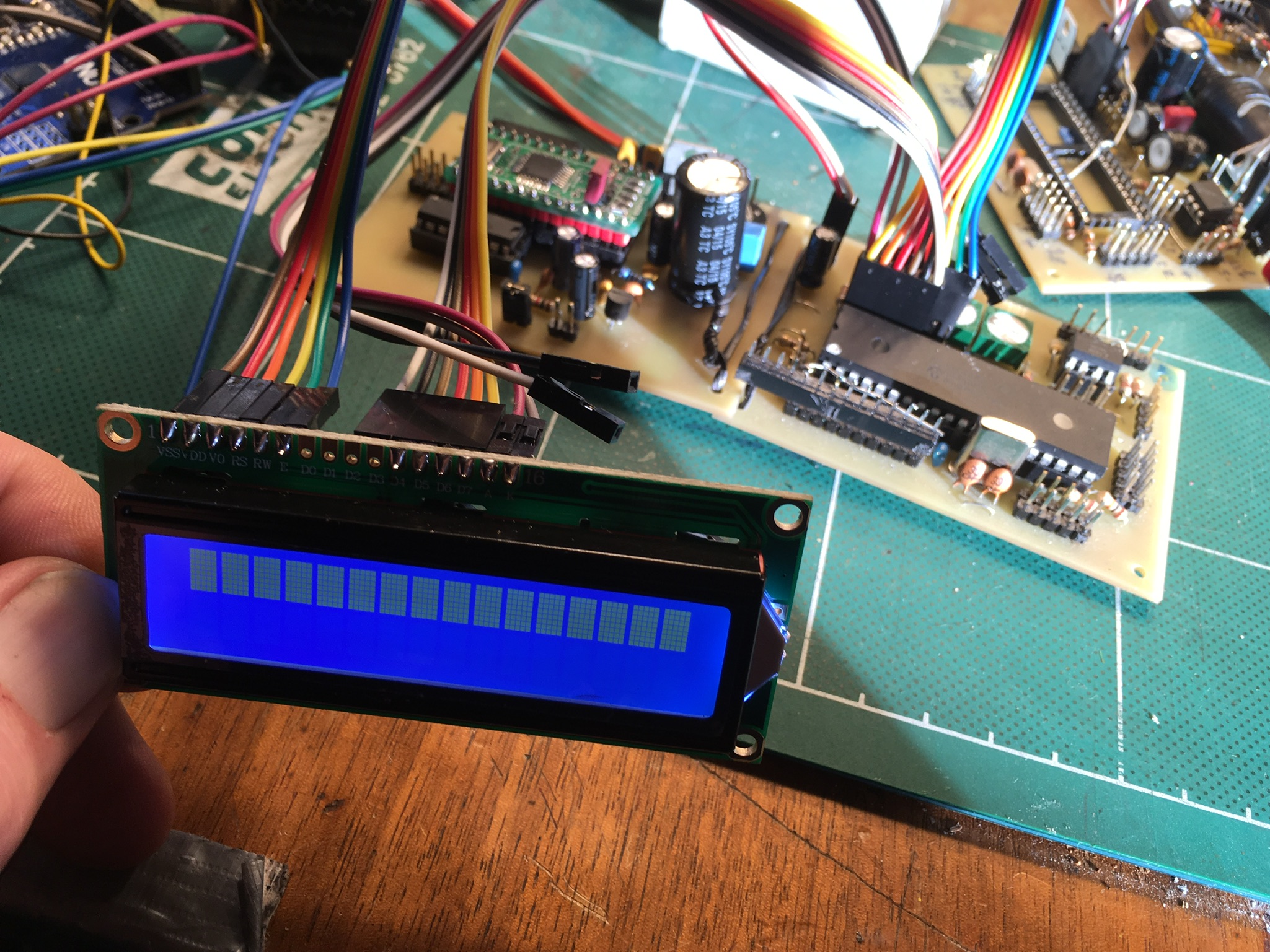
Hello everybody, I already made a Thread in the SID section but I came a bit closer and did see that this section is better. Core V3 with Pic X685 Midi with MIOS Studio works MIOS 1.9 uploaded, done LCD 1602A (HD441) tested with Arduino UNO, works, perfect Works also with Core, but no Letters, just blocks Trimmed Luma and Contr, just blocks... I think I read everything about using the LCD and it should show at minimum "something with letters" :) By default the HD441 LCD should be supported or do I just did not read and know something which would open me the magic door to see some letters on my LCD, finally?
-
I can´t confirm this, because I don´t have this board but the Cores should operate the same way. Normally this happens 1 time in a few seconds. Maybe it´s a wrong component? Have you proove the values? I dunno, still learning, every day.
-
Try this prog for flashing with pickit2 http://ww1.microchip.com/downloads/en/DeviceDoc/PICkit%202%20v2.61.00%20Setup%20A.zip. Or look here https://www.auelectronics.com/Q3.htm More Info and Schematic: ucapps.de/index.html?page=mios_bootstrap_experts.html
-
Hi, I have two Core modules and had 1 preburned pic which where working (midi and mios, fine). The last times I was trying to connect an unknown LCD and it break down my 5V, measured at J5 and midi was broken too, may reasoned by connecting B1 and B2 for Backlight. By disconnecting, midi worked fine again. I thougt may it's a low temperature display So I got another LCD Display, kind of sure it will work (from mikes-elektronikseite) But the same problem appeared and Mike told me I should use a 33ohm resistor between the direct voltage from the PSU and the backlight. And I tried also putting it at the B+ pin. May I did some other Playaround with my cables and damaged something. Midi wasn't working anymore and this is Pic based, because I have two Cores. I don't have a Pic burner but I bought one which is on it's way. I measured some 5v pins, which just make 2,5v, sure this is why midi won't work. So, is it possible to partically damage a Pic? May I damaged it before by connecting the first LCD wrong and later tried every possible pin combination. Edit It was possible to reburn the PIC. Also found a damaged part of the PCB. The unknown LCD is a 204A HD441. Vd and Vss is connected in a way I can´t find (not in the pin area)
-
"new" build (circa 2003 parts) - layout help etc?
Noise-Generator replied to EvLoutonian's topic in MIDIbox SID
Hi, you may find em by going to the new ones and look carefully if you find a link to the old ones. The SID module is here: modules->SID->scroll down to "a special page for the old version..." http://www.ucapps.de/mbhp_sid_old.html -
First I would check the core without the lcd and measure the outputs. Second, check if the pins to the lcd are connected correctly. Its not easy to give you a concrete answer because you don't explain what you did before, these are just standard advices.