

weasel
-
Posts
55 -
Joined
-
Last visited
-
Days Won
2
Content Type
Profiles
Forums
Blogs
Gallery
Posts posted by weasel
-
-
thank you so much, great advice! will get back later with results and thoughts! i'll order some troLED and get that fablab CNC going..
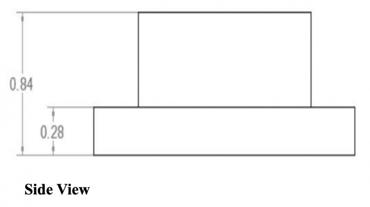
what do you think about the idea of just casting 0.84mm (LED height) of black resin or epoxy directly on the LED PCB, to surround the LEDs and thereby cover the sides, only leaving the top side open? either cast a thin liquid expoy or use something more gluey pasty and press it in/scrape off the top? i think the direct 90 degree side-to-side bleed between two neighbouring LEDs is my biggest culprit right now.
edit: what router bits are you using? dremel/proxxon stuff? i assume you run through a lot of them, breaking? any recommended brand?
-
@Antichambre man that finished frontplate looks so incredibly amazing, insane job, congratulations again. what kind of router & bit did you use to mill the PMMA? not sure the CNC at my fablab is fine enough.. not only are my measurements a good bit smaller but also i start realizing the laser cutter with its convexed cutting edge is not really precise enough for light channels like that.. so the biggest issues of translating your approach would be the holes in the black MASK layer, or rather the walls between the holes. @FantomXR i did some quick maffs, if we go 36>32 that will give me an additional width of the radial gap between each of the LEDs of 0.2-0.3mm, at the smallest most inwards point. so almost double what it is right now, i would have around 0.5mm at the smallest point which should make the masking much easier. might still have to CNC and not laser cut. oh and trotec FTW, they were the easiest and nicest to deal with too. innograv almost didn't take my business lol.
oh bruno if there is any chance you have some pictures of the MASK and WINDOW layer combined with the LEDs stuck through? or any more close up/side shots of the all-layer frontplate. that would be formidable oui oui.
i ordered a bunch of different epoxy/milliput/sealer combinations too though and still wanna try just casting/filling the whole 0.84mm height around each LED. anybbody ever tried filling frontplate LED holes with epoxy or similar?
EDIT: epiphany? what if i make a silicone negative of the fully assembled LED ring board, and then cast a theoretically perfect resin/epoxy mask from it? where do i learn about this haha. oh wait. i need a double negative casting shape. prolly all too much effort, i wanna make music not get into plastic manufacturing.
also i will try some ready made light pipes - anyboby has a good source for those? mouser etc start at 50ct/piece for the 1mm ones, that would be 70EUR per 4x1 board lol. have some regular 1mm and 1.5mm optical fibre cable coming too but i assume that will be hard to cut to size precisely and make it perfectly flush with the frontplate?
made some more lasercut cardboard masks last night, i think they came out better but probably not perfect. will test and report tonight.
@TK. thanks, yeah i somehow was sure you would consider expanding the code after we approached this barrier... i know you'd do that "im schlaf" basically. but here's my opinion: other than RGB LED rings probably nobody would ever want to connect that amount of WS2812 to a midibox. i personally would LOVE to be able to avoid the extra arduino, i just went there lacking an easier alternative, i didn't prefer it at all! so of course, midibox support would be great, but if i understood it correctly you want to reduce the amount of work you personally put in on midibox, and given that, i am also not sure if it is worth your time to work on this this driver. maybe you should save your much appreciated midibox time for someones more urgent problems? would love to hear other people's opinion on this. cause on the other hand the WS2812 is such a stable in the DIY world by now.
i'd very happily send you whatever display/mapping/ring-style code i have if you end up doing something. for you to laugh at, delete and redo properly.
EDIT 2 i can't stop staring at your frontplate bruno haha so beautiful you need to sit your ass down and finish these.
-
6 minutes ago, FantomXR said:
going down with the LED-count while keeping the diameter as is now.
haha man i keep coming back to that solution but i wanna try everything first to avoid it. i know i wanted 32 LEDs to start out with, but now that i got used to the higher resolution, i'd miss it. if i keep the same 5 bottom LEDs covered which i have to, it would only be left with a real life resolution of 26-27 LEDs... shoulda went with 0603 APAs maybe lol
seriously though, we might have to walk the 32 LED way.. give me a couple more days.
-
Hey @Antichambre, thanks a lot, good call on the forum post! I feel like this doesn't belong in the bulk order thread though so lmk if you want me to move this to a new thread before you or anyobdy else answers...
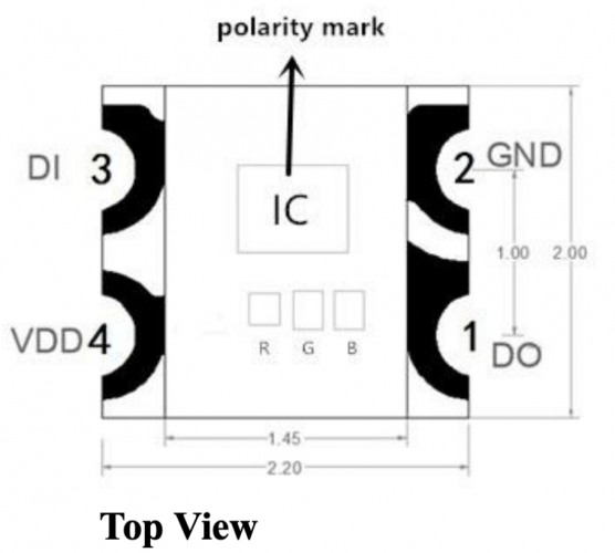
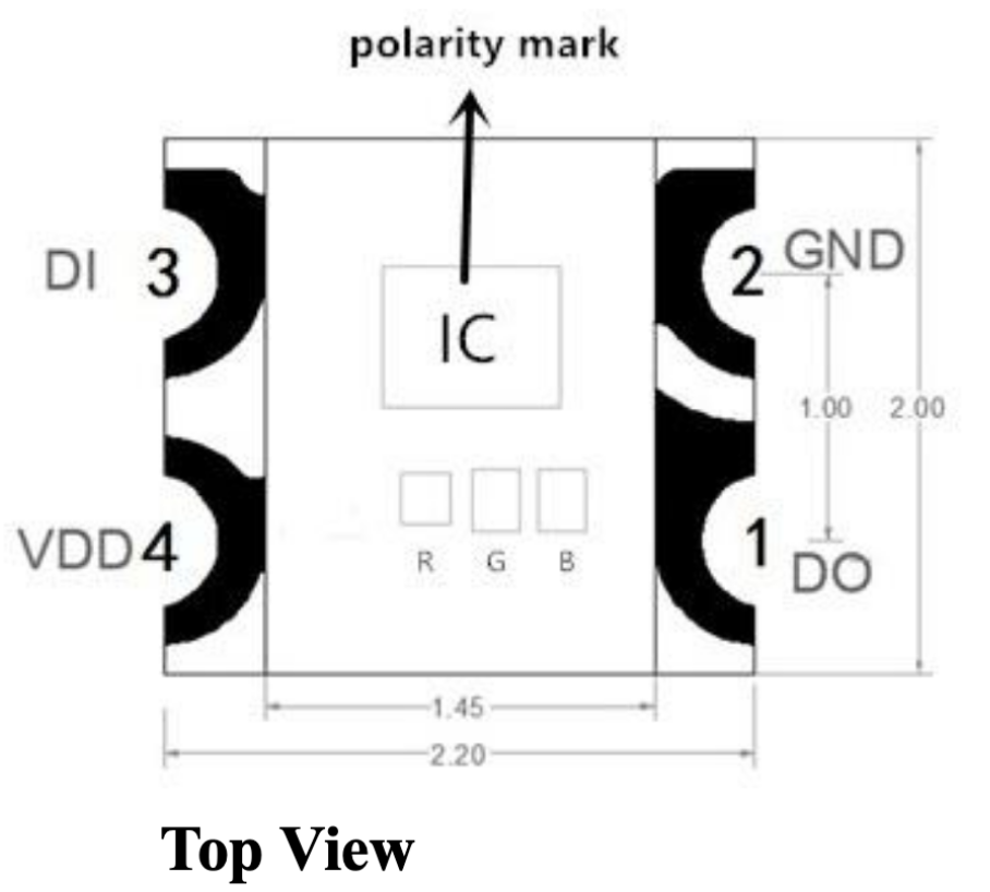
So i am currently investigating frontplate options and i realized some small issues with these 2020 LEDs: they are in a completely transparent housing, as opposed to the white housing with a top lense of the 5050 2812s. So naturally i get quite some cross bleed between the neighbouring LEDs, at highest brightness setting even up to 2-3 LEDs far. In real life it is not nearly as noticeable as on those videos i posted but i am still trying to optimize it.
Then of course i remembered your own glorious LED rings and the transparent inlays you sent me a picture of once. Would you mind in explaining in detail a bit more how you did them and if you think they are viable for my situation?
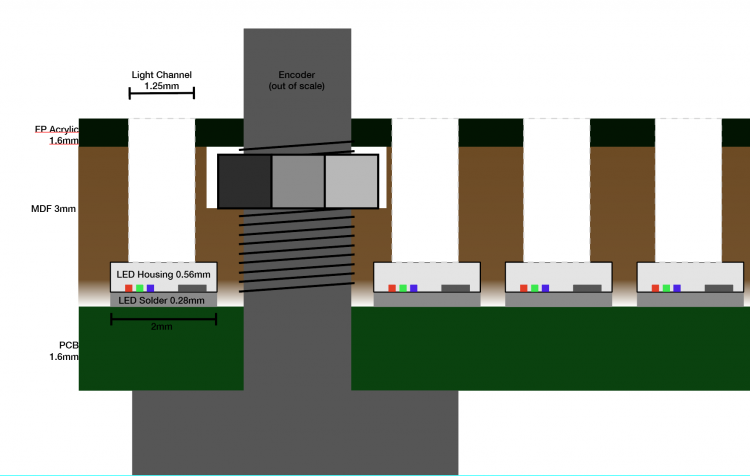
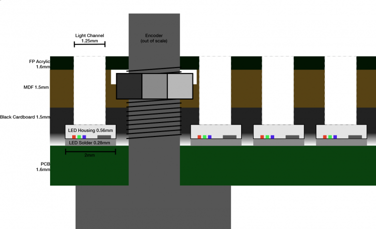
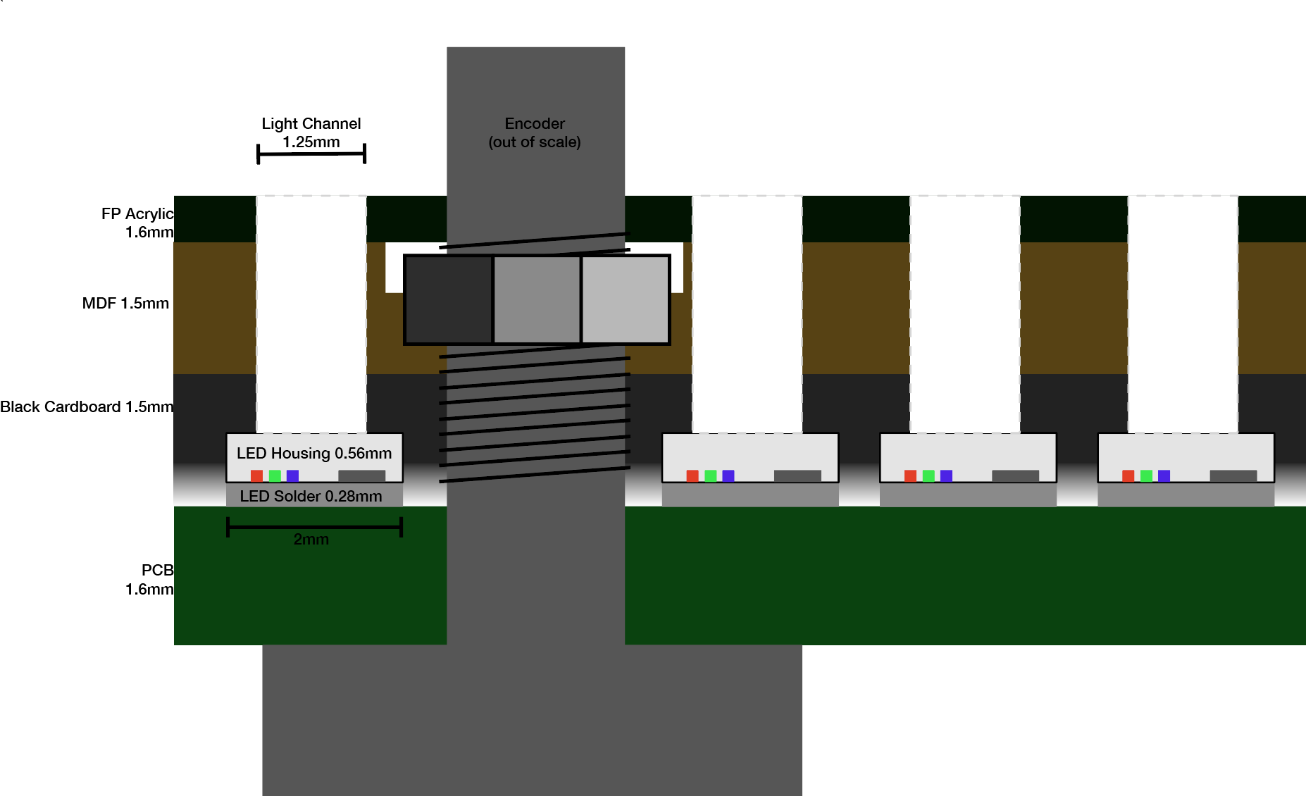
Following are some sketches of what i have so far and some ideas. The "light channel" drill holes got pretty long, 3.5-5mm over all, but that actually makes frontplate assembly super convenient and also should reduce the cross bleeding by creating a more narrow viewing angle. any input is welcome!
1. This is a description of what you see on the videos, what i started out with. just a 3mm mdf with 1.25mm holes for each LED, and another 1.6mm acrylic layer on top, same holes. they align nicely and sit right on top of the middle of the LEDs. The thin arrows show where i think most of the crossbleed comes from. the whole housing of the LED is transparent resin so the 3 tiny R G B LEDs all emit light in any direction of almost half a sphere.
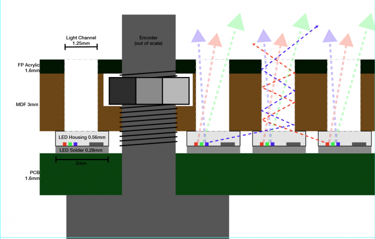
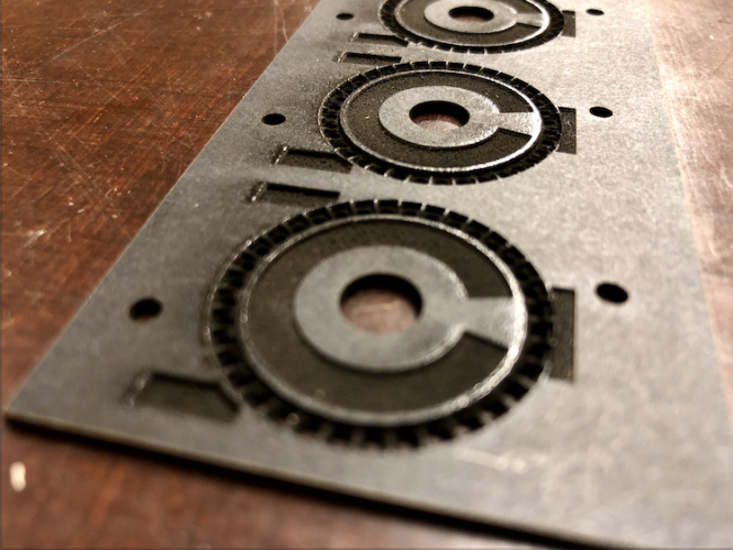
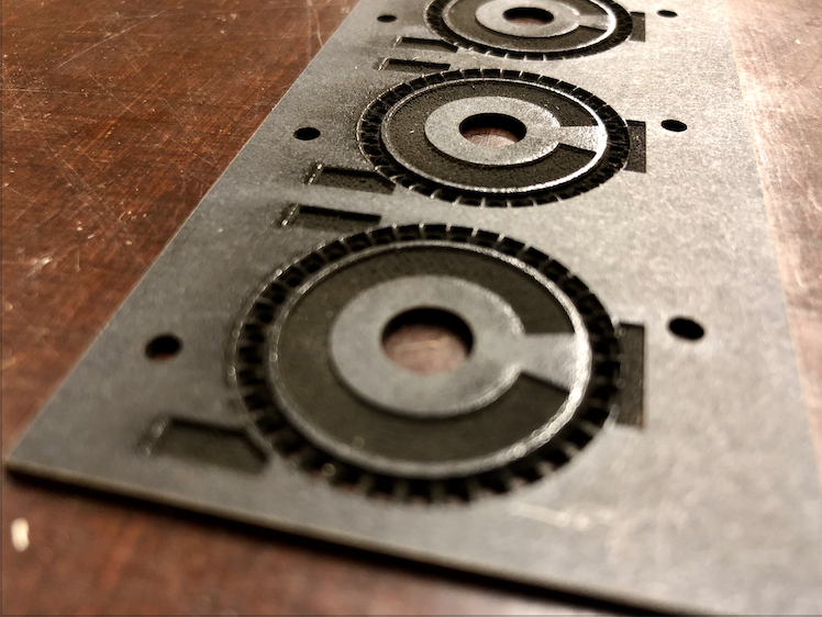
2. So the first thing i tried to improve it was to cut a negative mask out of MDF to enclose each LED, leaving room for the condensators and solder points.
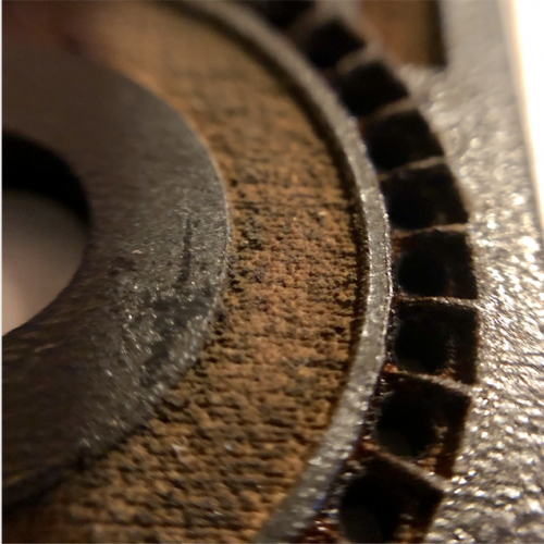
its black coated MDF and obviously the details are a good bit too much for the laser. but i am sure i could still improve on these first tries. it did improve the bleed a little but not to the extend i hoped for.
3. i tried the same technique but with black cardboard instead of the MDF, and the little bridges betwees the LEDs came out even better.
4. the next thing i want to try is different materials. i did a first cut of the same negative mask as above in solid acrylic but didn't get to test it yet. i have to play with the lasercutting margins and measures to make the fit as good as possible, eg. i left space for the extra solder points but not for the blobs of solder around the LED connectors. but right now i am more interested in alternative methods. what about using milliput or some other thick epoxy stuff, press it on the LED pcb so the top stays somewhat clear, and carve off remainders after hardening? something like this: (note: most likely my final front-frontplate will be aluminum..)
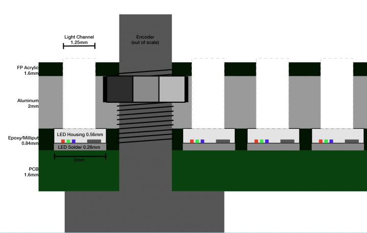
anybody has experience with using milliput/expoy like this?
another thing to try is the resin-based 3d printer in my local fablab which might be detailed enough to get a better mask going.
and yet one more idea is to get some thick lightproof acrylic paint and a tiny brush and try to paint the sides of the LEDs, or even spray paint it with circular masking tape on the top?
also i am not sure about how to fill the light channels in the frontplate, what you, @Antichambre did so beautifully with those inlays. i was also gonna try just fill them with epoxy and razer off any residue on the outside? or maybe get some 1.25/1.5 mm optical fibre, and stuff each LED hole with a 3-5mm piece that ends directly on the LED enclosure? might also help reduce bleeding.
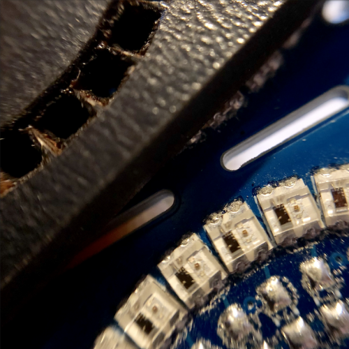
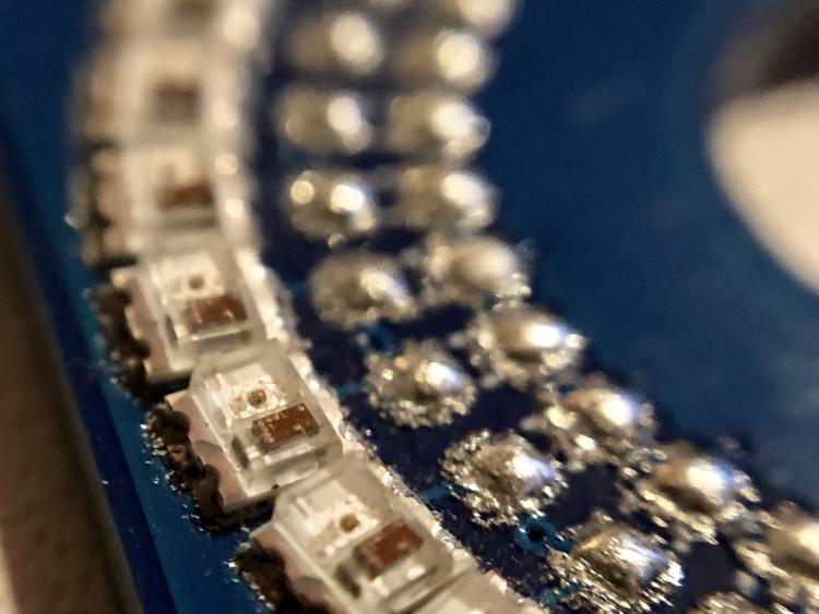
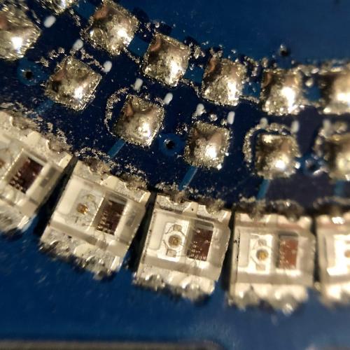
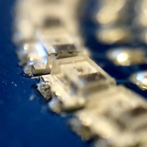
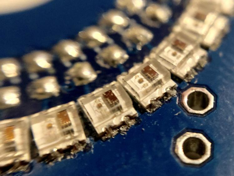
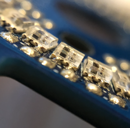
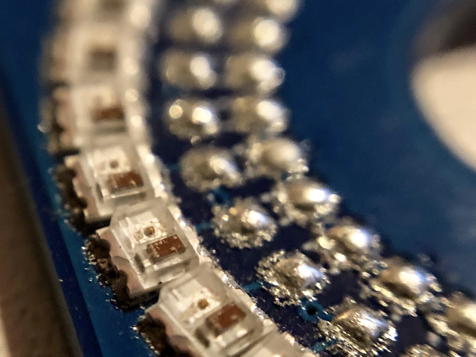
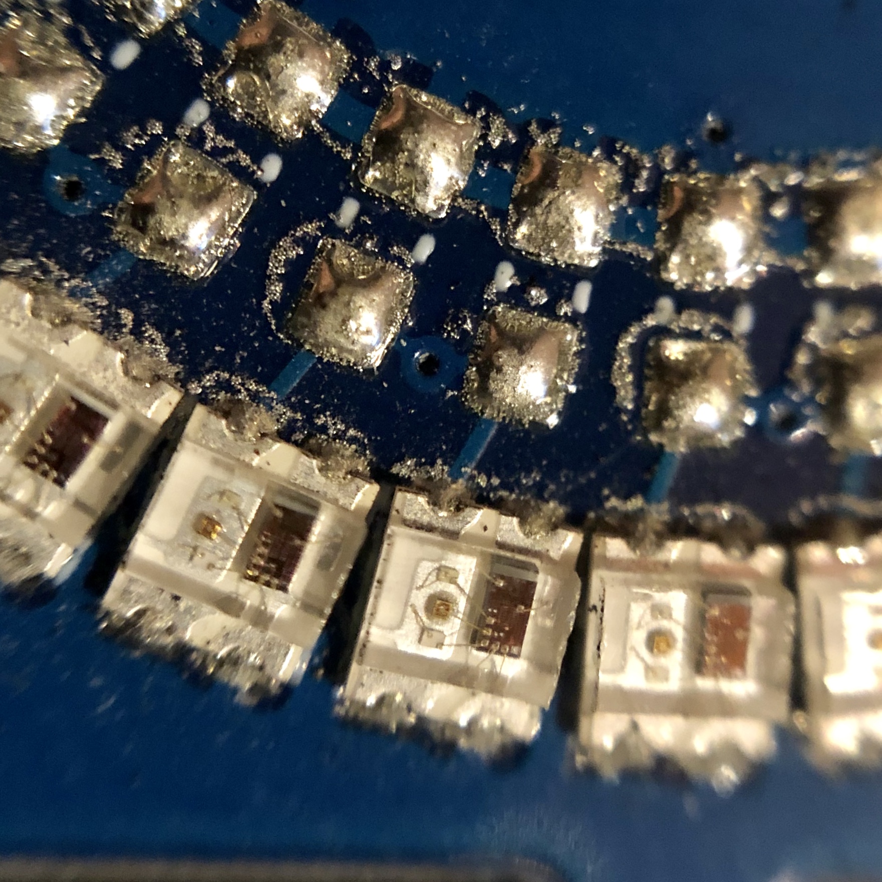
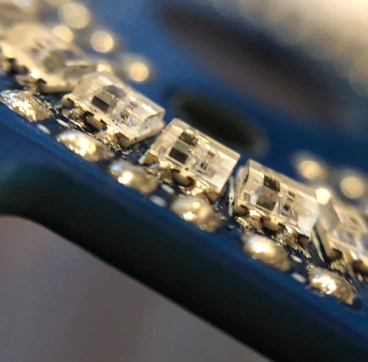
Here are some more pics of @FantomXR's beautiful prototype SMD assembly job, you can see the shape of the LEDs really good. in before questions: shot on iphone with a 10$ hama macro lens i just bought on impulse at the local electronics megastore. keep in mind these LEDs you see are 2x2.2mm small...
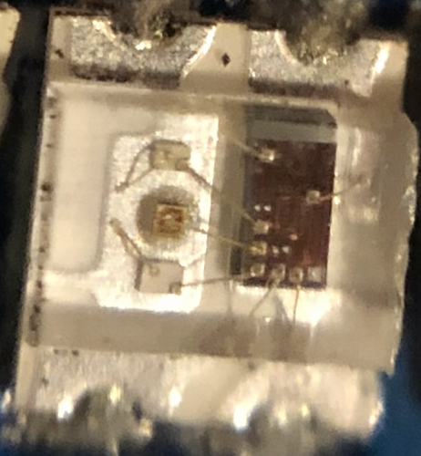
and to lighten things up here's another video, this time i added some shift functions.
-
On 5/28/2019 at 11:34 AM, ilmenator said:
Yay, Vegas Mode is already implemented!
of course, first things first!!
the manufacturer seems to currently have a discount on the assembly parts of the job, so prices will go down a bit! will update asap!
here's some basic music functionality tests:
-
here's a cute little video with a prototyping frontplate. bottom 5 LEDs are blacked out intentionally for classic "fake poti" use.
this right now is controlled via arduino, not midibox, since there were more convenient demo routines available.
frontplate is 3mm mdf, sitting more or less directly on the ws2812. top row has slightly bigger holes than bottom row. ws2812 running at 25% brightness....
-
Great work @FantomXR that picture looks absolutely terrific.
we will evaluate the design for a couple more days and run some more tests and then finalize the bulk order with updated prices, anybody interested can PM me now.
edit: fwiw, alternative method of driving ws2812 on the F7DISCO:
https://stm32f4-discovery.net/2018/06/tutorial-control-ws2812b-leds-stm32/
-
Wow this is amazing news, the OG just blessed us with a firmware update! I am pretty sure @FantomXR will get them running just fine now!
Thanks so much @TK. this will help alot and we should get at least 2-4 LED-Ring-Boards going. I'll send you some for reference once i have the production run!
I read through the mios32 ws2812 documentation and realized you need to use 48bytes per LED for the PWM DMA solution. I do understand the motivation behind this, saving CPU power, but is there a somewhat easy way to go back to other methods as described in the uC.net article you linked? Thinking of the "average" midibox tasks, i doubt it pushes an STM32f4 to it's CPU limits? Guess using the flash memory would wear it out too fast? I would love to implement it myself but that's way beyond my knowledge and time constraints, and at the same time i assume there is little need for other people to go beyong 300-400 LEDs. But how do other ie. arduino ws2812 drivers get away with just using 3 bytes per LED, on a much slower CPU?
Since for 40-50 encoders i need to adress between 1500 and 1800 LED - 72kb at 48bytes, ca 5kb at classic adressing - i guess i might have to just add a little arduino or similar MCU to control the ws2812. even the smallest UNO can handle 500 ws2812 at 60Hz, and the Due with its 3-4 serial lines should be able to run all 50 encoder-LEDs i need.
-
yeah since i'm coming form woodworking - maybe the OLED had to adjust to room temperature first

-
well after a million tests and power cycles yesterday i just turned on my main system power supply this morning and got this

so consider this case closed.
-
On 5/14/2019 at 10:51 AM, HUROLURA said:
This one could be the alternate an easier way to achieve our goal guys:
https://makeproaudio-shop.myshopify.com/products/dino-park-board
These look very interesting indeed. Not as obviously/conveniently freely programmable. I am currently building a synth on the axoloti platform. While rough around the edges the patching software for it is a really great balance between simple modular patching and hardcore coding. But the hardware is kind of outdated (same STM32F4) and the community rather slow these days. There are currently notions to develope upgraded hardware on an ARM m7 or other newer platform though.
sorry i just kind of crashed into this thread from a search result, not sure if this might have been discussed before or even is way off topic. oops.
-
I wired up my 7pin SPI 1306 according to this diagram using 1k res and 10u cap.

but i'm failing to get anything out of the screen. trying to just print text through the console lcd command, or the hello world program or even the NG init message.
i did set the correct LCD type in the bootloader:

there's this other old thread where someone had to connect the OLEDs reset pin to some other core connectors GPIO pin iirc? is that really the way to go, no convenient simple conncetion available?
i tried manually setting the reset pin to 0/3.3 via the testlcdpin command, no success. while manual, that should do the same trick as the GPIO pin reset above, right?
edit: i realized the J15 reset pin is connected to the DC pin of the OLED? so no manual reset this way?
i tried doing some measurements. core board soldering seems ok. power/ground voltages are also where i think they're supposed to be everywhere.
is there a page or list with debugging measurement points on the STM32F4 core board? DINOUT and AINSER 64 work for what its worth.
more pictures of my "circuit"


i realized in the above picture the SDA cable was in p4 instead of p6, that was not the issue though.
OLED supposed to work on 2.8-5.5v, i tried both 3.3 and 5v jumper settings.

yeah i know my soldering is "sub par"

GND and VCC from both j15 and the OLED going to the power strip on the breadboard, and the blue wire to the reset pin.
-
Quote
This calculation is not clear to me.
1 CPU cycle @ 168MHz is about 0,006uS
105 x 0,006 = 0,63uSyeah so at first i just randomly tried multiplying the result by two and then it was right and i thought "well that's one of these programming things where you just hack a '+1' and then it works" and never find out why.
but then i found this line
// timers clocked at CPU/2 clock, WS2812 protocol requires 800 kHz (1.25 uS period)CPU/2 clock
so it actually adds up. or rather divides up.
-
4 hours ago, FantomXR said:
// timers clocked at CPU/2 clock, WS2812 protocol requires 800 kHz (1.25 uS period)
#define WS2812_TIM_PERIOD       ((MIOS32_SYS_CPU_FREQUENCY/2) / 800000)
#define WS2812_TIM_CC_RESET     0
#define WS2812_TIM_CC_IDLE      WS2812_TIM_PERIOD
#define WS2812_TIM_CC_LOW       (u16)((WS2812_TIM_PERIOD - 1) * 0.28) // 28% -> ca. 0.35 uS
#define WS2812_TIM_CC_HIGH      (u16)((WS2812_TIM_PERIOD - 1) * 0.74) // 74% -> ca. 0.90 uS

// DMA channel (DMA1 Stream 0, Channel 2 - fortunately DMA1_Stream0 not used by any other MIOS32 driver yet...!)
#define WS2812_DMA_PTR          DMA1_Stream0
#define WS2812_DMA_CHN          DMA_Channel_2


#define WS2812_BUFFER_SIZE ((WS2812_NUM_LEDS+10)*24) // +10*24 to insert the RESET frame of 10*24*1.25 = 300 uS
IOS32_SYS_CPU_FREQUENCY should be 168000000, found in mios32_sys.h. But if I type this into a calculator:
(168000000 / 2) / 800000 = 105
So, why is 105 == 1.25uS? Doesn't make any sense to me....i might be too high or otherwise intelectually challenged for this, but fwiw your maths seem right - it is 105 CPU cycles which at 168 MHz amount to 1.25uS.
so at a 2 MHz clock rate it should be
(168000000 / 2) / 2000000 = 42 CPU cycles = 0.5 uS
which also seems to roughly correlate to the timings given in the datasheet which says 580nS-1uS
edit: ignore the last 3 lines, i am confused about which clock rate we actually need to get to, all data sheets say 800 KHz. so if it's not 2 MHz, do your own maths everybody :) but hey i did notice that 105 is CPU cycles and that it indeed is 1.25uS. That gotta be worth something, right?
-
prototypes arrived today!
(just posting to try and create a little pressure on @FantomXR for the proto-assembly
)
-
beautiful, funny enough i saw these yesterday, saying 1306 compatible and ordered some...
-
As another estimate, from what i gathered the update rate of the WS2812 limits one chain to about 500 LEDs, and at that keeps a refresh rate of 60fps for the whole chain which should be more than enough for musical controller values. So as already mentioned in our DMs, worst case we'll have to use 2-3 serial pins.
So while there might be limitations and downsides to our approach i am pretty confident it will still do just what i want it to do :)
-
Yeah as @latigid on said WS2812c is only a couple cents in the quantities we're buying. about 50% of the quoted prices goes into the assembly. @FantomXR thought about assembling himself with his reflow equipment but soon realized it will be way too many parts that need almost perfect precision.
Regarding encoders, the cheapest higher resolution ones i ever saw started at 30-40 euro. i'll personally most likely use regular 24 ppr ones with no detent which is perfectly fine for me.
i think based on the layout for these boards which we'll publish once finished, it should be easy for someone to remodel the upper LED layer to make a cheaper single colour version. or maybe there randomly are cheaper single colour chainable LEDs that fit the same footprint?
-
RGB LEDs allow to code a lot more information on a single ring - i can for example have several shift- or mapping applications on the same encoder with the changing color immediately and obvisouly indicating the function. you could also do classic VU style green-yellow-red structures indicating the "hotness" of a value, giving much easier and faster visual feedback over the current value. i think @latigid on did something similar with encoders with a transparent knob.
all the ready built WS-/or other RGB-LED rings have far to low resolution, you would get about 8 LEDs on the same diameter. as far as i know there are no hi-res (ie 24+) LED rings on a 2020 base, allowing for usable diameters.
edit.: just did some quick maths - 4 neopixel rings also actually aren't really cheaper than getting these perfect sized hi res PCBs fully assembled.
of course there are cheaper ways to get a LED ring but in this case i don't want to DIY to be cheaper, but rather better than commercially or previously available solutions.
-
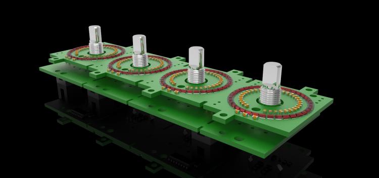
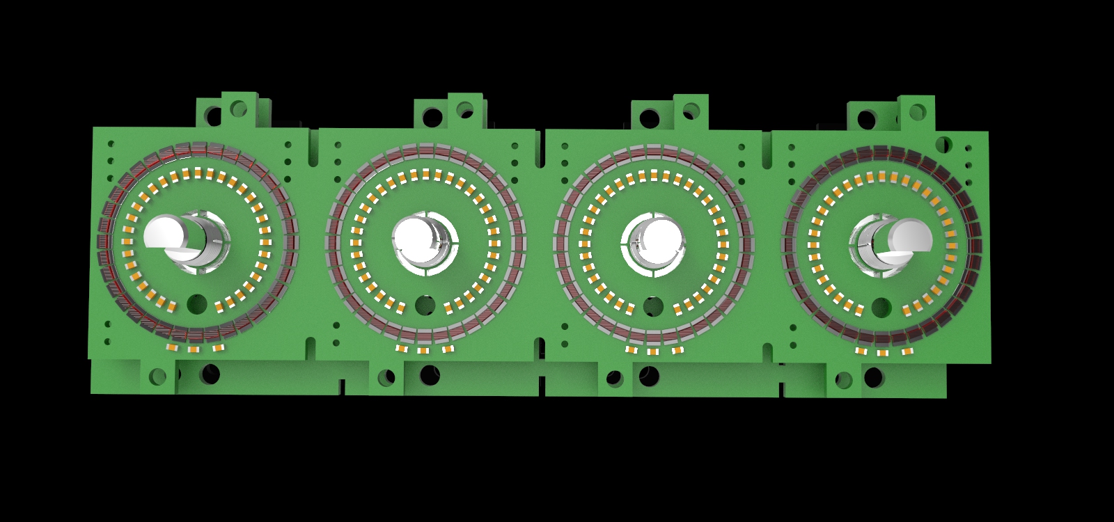
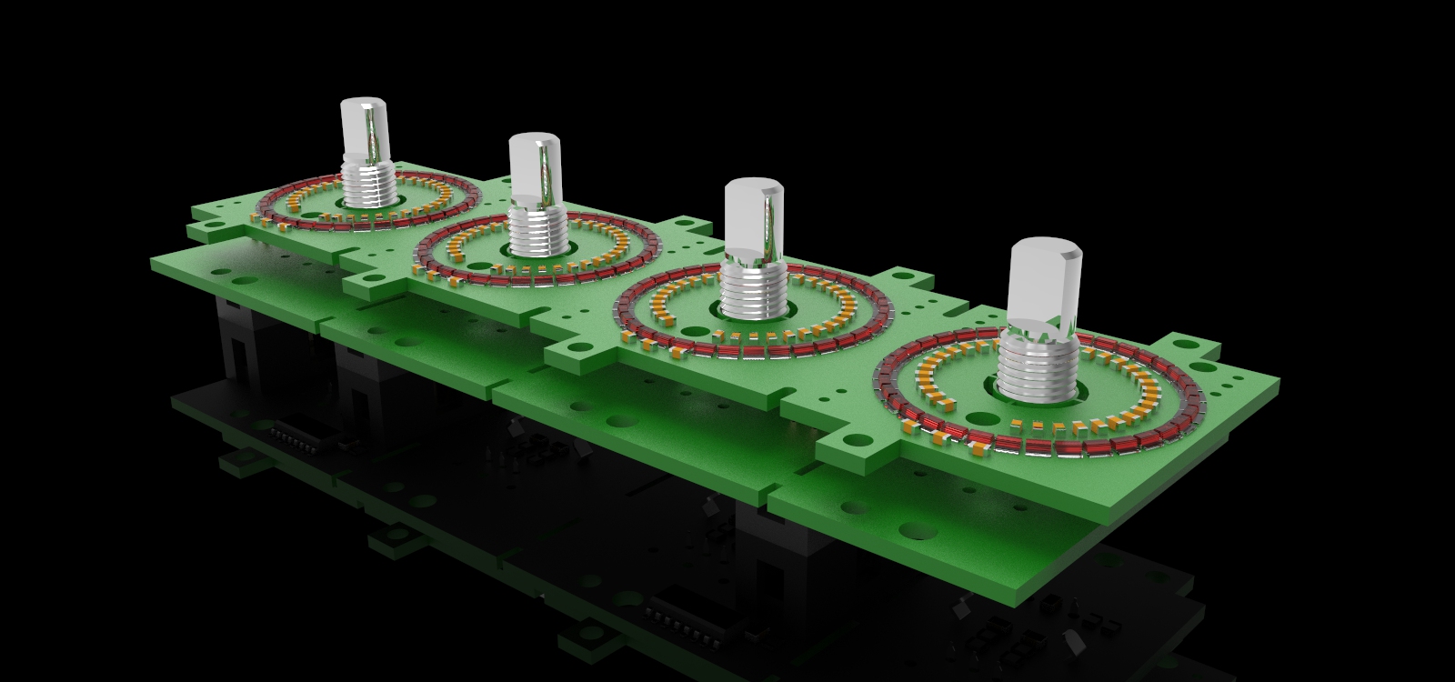
Hey there,As announced in the other thread I had the need for a 4x1 LED-ring/rotary encoder board. The incredibly talented @FantomXR helped me realize the design and together we came up with some pretty cool improvements on @Fairlightiii's (RIP) classic:- two layer sandwich PCB to get the SMD LEDs on surface level- encoder-slots compatible with both 11mm and 16mm encoders, with or without switch- two 74HC165 per encoder-board for direct connection to the core board, convenient midibox 10-pin IDC connectors- breakable design allowing to easily get 3x1, 2x1, 1x1 board configurations, partially leaving both broken parts usable/connectable/chainable.- Full ring of 36 WS2812c RGB LEDs in 2020 size, diameter of 27mm. The full ring allows for vertical or horizontal application as opposed to the classic 80% perimeter LED ring. 36 LEDs make up for the lost resolution.- additional power supply inlets for the hungry LED rings- distance between encoders is 33mm in the prototype, might change to 35mm for production, allowing for bigger knobs. Not a fan of the current micro-encoders.- option for whoever needs it to design a compatible OLED-overlay-board to use instead of the LED-Ring board and thereby achieve something similar to @Antichambre's great OLRE board.The design is not fully tested yet and we might make some adjustments but I wanted to put this bulk order up already so everybody gets a chance to see it before we order. Which will be as soon as the prototype has proven itself, hopefully in about 2-3 weeks. There is a number of questions to be addressed when the prototype arrived, ie maximum number of WS2812 on a single core board, overall power consumption etc. Obvisouly i am very happy about any ideas or constructive criticism regarding the design.Here is a price overview that we calculated from an offer we got on a slightly older design, so it might vary depending on the total order amount and possible design changes, plus a tiny shipping&handling fee. I will personally order around 50 each so would make it to the middle price bracket probably.Encoder board:50pc --> 10€ / pc.100pc --> 7€ / pc.200pc --> 6€ / pc.LED-Ring board50pc => 28€ / pc.100pc => 23€ / pc.200pc. => 20€ / pc.Yes these are pretty expensive compared to your usual diy pcb board, but we ruled out any self-assembly pretty early, given the amount of parts and also the sheer number of boards I personally need. So we will order these boards with all SMD parts fully assembled, if anybody is interested we could obviously also get some plain pcb boards made on the side.
So yeah please send me a DM or post in this thread if you are interested in ordering some of these.
Here are some nice renderings courtesy of the genius @FantomXR who might also chime in with schematics or if anybody has more specific technical questions.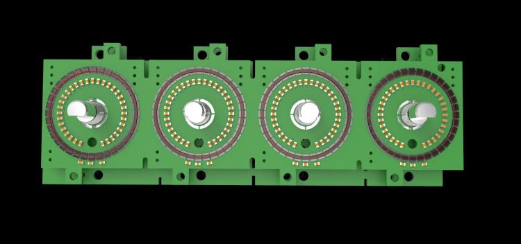
-
Thanks Peter, i understand by now that this community is somewhat closed in that “business” aspect. I now contracted a guy developing the new pcb circuit for me and will for now just get the 50pcs for me done, making extra ones and giving them away at cost seems like too much effort, also given thorsten doesn’t seem to be very responsive currently. I would easily pass all the requirements he listed but that useless facts i guess.
Obviously i will try to document and publish my stuff as much as possible, but spending substantial time finding out what the community wants or needs etc is out of scope for me right now. I don’t have “many years” to build my synth. Also the demand was secondary to me as i don’t have the intention to make money on this and i’m not in a rush to recoup the production investment either. Developement cost is on me too, which is high cause i now have to hire a professional given the lackluster help from within the community so far. I am making these for myself and just wanted to make spare ones for whomever might need.
Cause at the same time from a user point of view i am 100% sure a lot of people would be interested in a smaller or even modular/breakable encoder/led option. Show me a hardware synth that has 16 uniform knobs in a row. Even worse 8x8. But that’s a different discussion.
i am currently assembling my core and i/o boards and should have the circuit design and a prototype for the enc/led board within 2 weeks, will get back for feedback then. The actual synth engine is 99% finished too, just the controls are missing.
have a nice day everybody!
-
Mike's ceased his midibox business, Jörg who has the leftover stock is getting me the DIN DOUT for now but the STM32F4 is only to be had from the US right now.
I have a more general question about midibox and general open source guidelines, as i am all new to this. whats is the process if were to produce midibox based boards extension boards like described above, make twice the amount of my personal need and have the other half commercially sold through the usual suspects, at cost though without any earnings for me. do i have to get approval from thorsten or anybody? i assume some kind of crediting according to whatever open source license has to happen? can someone take me by the hand here please? it's been kind of hard to get any kind of positive or encouraging response from most of the people in the midibox supply scene i spoke to so far.
-
damn i just saw there's no DIN/DOUT or analog I/O modules on midiphy either. got some analog from MA coming but is there any place right now i could get DIN/DOUT from?
-
haha damn you guys beat me to it. i swear i searched this forum and the internet and couldn't find midiphy or any serious EU supplies.
this board looks very promising, what OLEDs are you planning to use? character ones?
when do you think it will be available?


LRE 4x1 breakable RGB LED-Ring/Rotary-Encoder PCB bulk order
in Bulk Orders
Posted · Edited by weasel