TK.
-
Posts
15,248 -
Joined
Content Type
Profiles
Forums
Blogs
Gallery
Everything posted by TK.
-
It could be important to cast a value to the correct type before doing such operations. A code snippet would help to understand what is going wrong. On the other hand: If your value is an Int anyhow, and you only want to reduce the resolution to get a 7bit value, why not using "intValue / 1000"? Float operations are expensive (performance wise), but fixed point divisions (and multiplications) of integer values are fast since they are supported by the hardware. Best Regards, Thorsten.
-
Everything correct. Possible errors: - Jumper J26 not stuffed - Resistor Array R32 not stuffed - wrong wiring between CORE_STM32::J19 and AOUT_NG - +/- 12V not connected to MBHP_AOUT_NG module (you could measure the low range voltage of the TLV chip directly at JP1 and JP2, see schematic) - JP1/JP2 jumpers of AOUT_NG module not stuffed When testing the CV voltage, the sequencer should play *different* notes (otherwise you won't notice a change) e.g. with c-1, C-0, C-1, C-2 the CV channel should output 1V, 2V, 3V and 4V Best Regards, Thorsten.
-
I know the location and some of the guys... ;) The projections are very impressive, well done! Best Regards, Thorsten.
-
There is a simple answer: the simplified (s)printf function of MIOS32 doesn't support %f See also http://svnmios.midibox.org/filedetails.php?repname=svn.mios32&path=%2Ftrunk%2Fapps%2Ftutorials%2F003_debug_messages%2FREADME.txt Workaround: write DEBUG_MSG("%d.%03d", (int)floatValue, (int)(floatValue*1000) % 1000); Best Regards, Thorsten.
-
I remember that Kurt did something similar, but without SID based sound output. Here a link to the documentation and a video: http://www.midibox.org/dokuwiki/doku.php?id=mblight_mind-machine Of course, it could be possible to output sound as well. MIOS doesn't prevent you from implementing something like this ;) Best Regards, Thorsten.
-
You don't need to recompile the firmware. Just edit your MBSEQ_HW.V4 file on SD Card: # define the AOUT interface which is connected to the core # 1: a MBHP_AOUT module # 2: up to 4 (chained) MBHP_AOUT_LC modules in 8/8 bit configuration # 3: a MBHP_AOUT_NG module AOUT_INTERFACE_TYPE 3 [/code] unmount the SD Card on your PC or Mac and reboot the core to reload the file. Ensure that you are using the latest firmware release. The AOUT_NG module wasn't working in Beta19, I fixed the driver and tested the AOUT_NG module in the latest beta20 release (as documented in the ChangeLog) Best Regards, Thorsten.
-
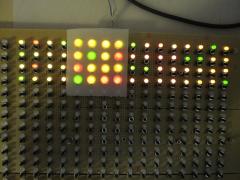
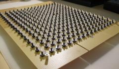
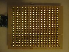
Follow the progress of the BLM16x16 (+X ;-)) project
-
-
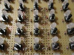
From the album: TK: BLM16x16 + X
-
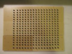
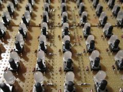
From the album: TK: BLM16x16 + X
-
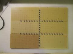
From the album: TK: BLM16x16 + X
-
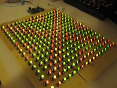
From the album: TK: BLM16x16 + X
-
From the album: TK: BLM16x16 + X
-
From the album: TK: BLM16x16 + X
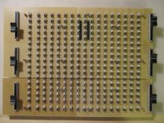
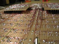
Please note: soldering such filigree wires is time consuming and requires some dexterity. It will work perfectly with double layer PCBs, but if you really consider to build the BLM on a prototype board like me, it's probably easier to add sockets at the bottom of the PCB (thats my conclusion after all the work) -

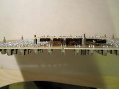
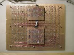
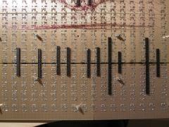
Later we will use such 2-row SIL headers to mount the SRIO boards
TK. posted a gallery image in Members Gallery
From the album: TK: BLM16x16 + X
-
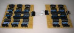
Usage of 2-row SIL headers to ensure the correct distance between boards
TK. posted a gallery image in Members Gallery
From the album: TK: BLM16x16 + X
-
Yes, it's possible to connect 4066 to a DOUT and to use them as bidirectional switches. Connect Vss to ground, Vdd to 5V (*), CONT A/B/C/D to digital outputs of a DOUT module, and the SW pins to the circuit that should be controlled. (*) Vdd can be higher if you plan to control a circuit that works at higher voltages - it should be at least the target voltage. Only disadvantage: in distance to relays (or optocouplers) they are not galvanically separated from the digital circuit (MBHP_CORE, MBHP_DOUT), but if this doesn't matter you will be happy with this approach. If bidirectional voltages are switched, you have to shift them to a mid level. Audio signals will get some additional noise. If galvanic separation or Audio signal quality is a *must* for your application, I recommend reed relays - they are small, reliable and silent (but they are also expensive...) Best Regards, Thorsten.
-
I will add the possibility to assign a UNDO button in the next firmware. But it won't be preconfigured in the standard setup, people have to decide by themself if they find a direct access to this function useful. Personally I prefer clear before undo. Not only because I use the clear function very often, but also because a dedicated undo button could imply that it works on *any* change. But Undo works only on a small number of functions that are listed in the utility menu. I don't plan to provide undo for any parameter changes. Best Regards, Thorsten.
-
Trigger values cannot be changed, they are statically defined. The trigger pattern of the selected layer has to be edited with GP buttons. Yes, select the range with the encoders Yes, select the target position with the encoders F1 isn't assigned to the Clear function, something seems to be wrong at your side. Yes, I could provide an UNDO button function if really required. Works at my side. I remember that there was an issue in a very old firmware release - are you using the latest version? press the SELECT button for additional options and configuration You are probably using an old firmware Works at my side - old firmware? Currently you have to create /sysex with a PC/Mac anyhow to copy some files /midi is created with the export function if it doesn't exist yet. Otherwise you have to create it with a PC/Mac anyhow to copy some files. Group # and Location # belong together, therefore this item is marked with multiple LEDs. Best Regards, Thorsten.
-
Since Wilba prefers acronyms: HB2Y! Best Regards, Thorsten.
-
It's related to the cable impedance. Best Regards, Thorsten.
-
Thanks for the work! Could you please bring this into the Wiki? This would allow me to edit/correct/enhance the comments Otherwise I would have to edit your posting and update your .html attachment. But this would only be possible for me (as administrator), and not for other users who also want to add corrections. Best Regards, Thorsten.
-
No, the ALL button has a different function (not related to manual trigger). You can select multiple tracks by pressing&holding the TrackSel button (tracks selected with GP buttons). Alternatively press&hold a track button, thereafter press additional track buttons... Best Regards, Thorsten.
-
The cables shouldn't be longer than 20 cm. Longer cables could work, but you have to try this on your own risk. If LCD cables are too long, the displays won't work at all, or will sometimes output random values. If SRIO cables are too long, LEDs will start to flicker, random button functions could be triggered, or all buttons/LEDs could be shifted by 1..2 positions. Best Regards, Thorsten.
-
I know :) There is no faster way, but you can store your drum map (and labels), resp. the complete track configuration, in a preset file to re-use it later for other tracks. Presets are not part of a session, but globally stored in a special folder on SD card. In other words: after you prepared the drum maps for your gear, you won't have to do this time consuming work again. Just move an encoder to change the value. Please create a separate troubleshooting topic if you are not able to find the error. The "IN port" is a global selection for the physical MIDI interface (and MIDI channel) you want to use for transposing tracks. E.g., by setting it to IN1 your keyboard has to be connected to the first MIDI IN port of the MBHP_CORE_STM32 module. Use the integrated MIDI monitor of MBSEQ to check if MIDI events are received. Yes, but if you restart the sequencer the track will be on sync anyhow. "Sync to measure" can either be used as a permanent setting which sometimes leads to interesting results (especially when unequal divider values are used, but also for progression parameters) Or it can be used to sync the track once only after divider values have been changed (after the sync happened you have to disable the function), so that the sequencer doesn't have to be restarted. Alternatively the "one time sync" can be triggered by pressing the SELECT button in manual trigger page as you already noticed. :) Of course, the track length should be 24 steps to align with other tracks that are playing 16th notes. I second this! Hint: you can select multiple tracks and control the position for all at once. Planned additional feature for this page: pressing two GP buttons will create a loop between these buttons until they are depressed again. :) Best Regards, Thorsten.
-
15% Abweichung ist schon ziemlich ungewoehnlich - andererseits: wie hast Du den Widerstandswert denn gemessen? Dein Messgeraet hat ja auch eine gewisse Toleranz. Analoge Messgeraete sollte man vorher bspw. kalibrieren - und eine veraltete Batterie, die nicht mehr genuegend Strom liefert, koennte den Messwert ebenfalls verfaelschen. Fuer den S-Video Ausgang ist die Abweichung uebrigens tolerierbar. Falls das Bild immer noch uebersaettigt sein sollte, schalte einfach zu dem Moechtegern-300 Ohm Widerstand einen 47 oder 100 Ohm Widerstand in Reihe. Gruss, Thorsten.