Wilba
-
Posts
3,310 -
Joined
-
Last visited
-
Days Won
2
Content Type
Profiles
Forums
Blogs
Gallery
Everything posted by Wilba
-
I need the exact spec of smash's led's! I'm 12 short!!
Wilba replied to dubka's topic in MIDIbox SID
Wow! that picture is almost identical to the beer icon you still haven't clicked on! <---- see the beer icon? ;) -
I need the exact spec of smash's led's! I'm 12 short!!
Wilba replied to dubka's topic in MIDIbox SID
Actually I'm already too drunk to work out how much 24 LEDs plus postage would cost... just buy me the bloody beer already. -
How do I use the interconnections test? (SID R doesn't work)
Wilba replied to pingosimon's topic in Testing/Troubleshooting
I guess "nearly pooped pants" means she all works now. Congrats. Wait till you hear 8 SIDs screaming in superpoly mode... you'll look like this: -
How do I use the interconnections test? (SID R doesn't work)
Wilba replied to pingosimon's topic in Testing/Troubleshooting
MB-SID can have four Core modules, each running it's own engine. That's what is referred to as SID 1, SID 2 etc. Your second SID module connected to a Core is the "Right" one of a Left,Right stereo pair. That's what is referred to as SID L/R in params for that SID engine. You'll see it in the mod matrix (mod target can be -/-, L/-, -/R, L/R), in the Shift menu (view/change params for left, right or both)... One unintuitive but very cool example: The Inv2 value on a mod matrix row will invert the value for the right SID. FYI there's no "recognizing" - a Core can't tell if a SID module is connected. It can only "recognize" other Cores connected on the CAN bus... i.e. to operate in master/slave fashion. Hence the "1***" is correct, you only have one Core. Interconnection test is explained in the main.asm I think... basically you send mod wheel messages to control which SID pin is being set high, and check that this pin is 5V and the others are not. The LCD shows which pin is being set. Try the patch editor... you can then do stuff to check if left and right SIDs are doing different things... perhaps easiest thing to do is run the init patch for Multi engine and hear three voices come out of each channel. -
40x2 Green-on-Black Optrex Displays - ORDERING INSTRUCTIONS
Wilba replied to fussylizard's topic in Bulk Orders
LCDs received today! :) -
It's open as such... but nothing is being done yet until Doug and I get some time to sort out the case/panel design and he has time to make them.
-
The quick answer is... the 74HC165 go between two resistor networks (and inversely, the 74HC595 go where there aren't resistor networks). Apologies for lack of parts list... that's what you get for being "Bleeding Edge Prototypers", no build instructions! ;)
-
I need the exact spec of smash's led's! I'm 12 short!!
Wilba replied to dubka's topic in MIDIbox SID
I haz spares of SmashTV's yellow and green 3mm LEDs. Buy me a beer, I'll send you 12 of each. <---- see the beer icon? ;) -
Check out NorthernLightX's PSU design: http://www.midibox.org/dokuwiki/doku.php?id=northernlightx
-
MB-6582 Ventilation & Combined Analog Input and Feedback
Wilba replied to Syntax's topic in MIDIbox SID
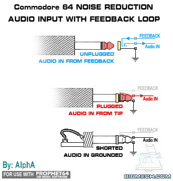
You might want to consider what the "inventor" of feedback pots on C64s did... see the attachment because his website isn't working. http://www.bigmech.com/misc/c64mods/noisereduction.html You can't do it exactly like he did because he's using mono plugs/sockets. My suggested setup for MB-6582 is a little different - the feedback pots are connected to audio output and ground on each "end", and the wiper goes to audio in, thus giving you the ability to attenuate how much output goes into the input. Perhaps instead of connecting one side of that pot to ground, you connect it to a pin of a switched audio input socket with the sleeve pin grounded. Thus when the audio input socket has no plug in it, the pins are grounded, and the pot lets you scale between no feedback and total feedback. When there's an audio plug in the socket, the pot lets you scale between audio input signal and total feedback. With a 500K or 1M pot, the two signals being mixed won't affect each other, I think... I'm not an expert at these things, sorry... you can always test the theory before committing to it. Anyway, it's just a crazy idea that could mean you don't need switches or big panel changes. -
That only works for low current situations... each diode is dropping 0.6V-0.7V (I forget exactly) and also dissipating heat. It is a bit of a hack that TK suggested, and it's better than using 1W resistors, which also dissipate heat, but their voltage drop depends on load, whereas the diode is a fairly constant voltage drop. I can get away with it because the current through the 7805 is only 300mA, so the heat dissipated by each diode is small, and I want less load on the heatsink because there's not enough space for a bigger one. In your case, a bigger heatsink is a better solution I think.
-
Batches #1 to #4 are now all reserved. I received 60 pre-orders in the 48 hours since the midibox.org blog entry, and the subsequent Matrixsynth and Synthtopia articles. Things have gone quiet now, just as the magic 100 number was reached, which is a good thing actually because I don't like telling people they've missed out (for now), especially for such embarrasing reasons as I don't have enough time and spare cash to make kits faster. :-[
-
MB-6582 Ventilation & Combined Analog Input and Feedback
Wilba replied to Syntax's topic in MIDIbox SID
Heatsinks dissipate the heat away from the thing they are connected to and into the air... so heatsinks don't generate additional heat. You don't really need the fan, that was added for eye candy really :) but you should put some slots/holes somewhere on the case to let hot air escape. I cut slots on the right side of the bottom half of the case (you can see it in photos). If you added slots like this on both sides, and more of them, that might be sufficient. Instead of cutting slots, I once considered cutting out that whole area and replacing with some mesh... perhaps that idea might be more appealing than cutting slots which is time consuming. It would be interesting to see exactly what you propose... can you perhaps sketch your idea on top of a photo of MB-6582? Also I am wondering, if you want four analog inputs, why have you decided not to use the four holes above the audio outputs (where feedback pots go)? Having both audio inputs and feedback pots doesn't really work well, the feedback pots (as I suggest using them) are connected to the SID audio inputs and ground the inputs when you're not using feedback. There's no neat way of doing both (i.e. a grounded audio input socket and a feedback pot routing audio output into audio input). -
It certainly sounds like it's failing under load... the fact that it happens after the 3rd set basically means when your SID load is over 400mA then it fails. My guess is there's nothing wrong with the PCB itself, or I should say it's pretty unlikely you have a short that's causing the PSU to fail exactly when the SID load is over 400mA. What exactly are you using to power the MB-6582 PCB?
-
-
The process is pretty simple... you can go on their website and download a starter pack, so I don't need to explain the details really... My workflow is essentially: - design what I want in Inkscape using mm units everywhere, lots of guidelines, and 0mm stroke lines, using Outline mode so you can see them - make a "Ponoko" version of the design by replacing the 0mm stroke lines with the right setting for laser cutting (i.e. 0.003mm blue lines) and the other stroke/fill types for engraving. - copy and paste these into the three SVG files that Ponoko provides, which have an orange border showing where the "safe area" is. Arrange to minimize waste and save as new version. - upload this file to Ponoko and get a price. If you want something that looks more like an FPE panel (i.e. single-stroke DIN1451 like my SEQ panel) then you can do this with a few extra steps - create the text in a CAD program using a vector font, export to SVG, then optionally do some stroke/outline magic to create a three-stroke engraving (i.e. the original vector font plus a rounded outline). This will produce a very clean, sharp-edged engraved text that can be paint filled. If you want text smaller than 2.5mm high then you can skip the outline step and just duplicate the same vector font lines (i.e. so the laser goes over it twice). That will make it go deeper but not much thicker. I recommend Inkscape 0.47 (it's still not released as of this post, but using the devel build gets you some awesome snapping improvements which really helps with this CAD-like work).
-
How do I use the interconnections test? (SID R doesn't work)
Wilba replied to pingosimon's topic in Testing/Troubleshooting
Continuity mean checking they're connected. There's often a mode on the multimeter that beeps when you touch the probes. On mine it's marked with a diode symbol because it also tests voltage drop of a diode. Use that to test each pin of J2 on SID L is connected to the same pin of J2 on SID R. If your multimeter doesn't have this mode, just test resistance is 0 Ohms (it won't be exactly 0 Ohms, but you know what I mean). You could try the interconnection test also... testing that the shift registers etc. are outputting high and low signals. Unfortunately, MIOS Studio doesn't have something to send exact Mod wheel messages, so you have to use something like MIDI-OX. The LCD will show you what pin is being tested, refer to the schematic to find it on the PCB. -
How do I use the interconnections test? (SID R doesn't work)
Wilba replied to pingosimon's topic in Testing/Troubleshooting
OK that proves Core:J14->SID:J2:SO is not the problem. It's possible that some of the other wires to the right SID module are open or shorted. For example, if the SID clock is not working, the SID won't actually run. Or if the comms signals aren't getting into the shift registers, then data is not getting into the SID. With everything connected, check for continuity between the pads of J2 on each of the SID modules (except J2:SO), since all these should be "common" and connected to the same pins on the Core. Also... are the cables of equal length? Is it a chain (Core->SID L->SID R) or a Y-shape (Core->SID L, Core->SID R). Upload a picture if you can. (Click on "Additional Options..." when you post). -
Good to hear, Xem!
-
Well for people in USA and New Zealand (where there are Ponoko "hubs"), the shipping is cheap and so the overall price for prototyping is excellent. For me in Australia, it's close enough to NZ for shipping to be reasonable too. For Europe, it sucks majorly, the shipping from either NZ or USA is ridiculous, basically because they have to use a courier. Example: I'm ordering the smallest size panel (181mm x 181mm x 3mm) to test this custom material, to ship to me from NZ is US$6.38 + US$2 handling. If it was to Europe from US, it would be US$59.90 + US$2 handling. You can see the shipping costs here. It's unfortunate that there's not a Ponoko hub in Europe yet, because I'm sure it would be a huge success, since the NZ hub seems to be doing fine and is probably mostly servicing such small populations as NZ and Australia due to the high shipping costs to anywhere else.
-
Yeah, registered post for <250g is a ripoff price... for the larger weight categories it's only $5.20 more than regular airmail.
-
BTW Ponoko are great to deal with when you want a custom material... I requested a specific black satin finish acrylic and they tried to get that but it wasn't available, so to show me the closest thing their supplier could offer, they sent me a video clip: http://www.youtube.com/watch?v=hPjqny-jq0E Finally an excuse to upload something on YouTube! :)
-
Ooof... I missed that bit about primary side :-[
-
are you saying you don't see what I see? (see attachment)
-
Cool! If you like it that much now, your head's gonna explode once you put in the step LEDs ;)