

Wilba
-
Posts
3,310 -
Joined
-
Last visited
-
Days Won
2
Content Type
Profiles
Forums
Blogs
Gallery
Everything posted by Wilba
-
Arctic Silver 3? ROFLMAO :D
-
m00dawg: good plan... I recommend taking out both regulators and replacing them.... perhaps first you can try bending them both up, taking off the heatsink and cleaning the lot, and see if that really was the cause of the short. It's possible to bend them back down and attach the heatsink, although maybe this won't result in as good a contact with the heatsinks, but good enough.
-
Yes, for now they show the gate on/off state in multi engine, or the pitch of each oscillator in lead engine. As long as they are all aligned the same way and matching the PCB outline of the LED (flat edge to the right) then you won't have any problems.
-
The purpose is for looking cool in TK's demo video! ...people might think that's a joke but I'm serious.
-
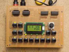
They are an extra set of 22nF capacitors for the SIDs. Only batch #1 received them. Details were in the "ORDER POSTED" email I sent. This is the 2nd prototype PCB, the only differences are some labels, but for the purposes of showing default jumper settings, it's adequate:
-
"Any sufficiently advanced technology is indistinguishable from magic." - Arthur C. Clarke
-
PM SENT! :thumbsup:
-
For future reference, I like pictures of sammichSID next to other gear (keyboards, synths, bikini-clad supermodels). If there ever will be a gallery of all 200+ sammichSIDs, it's going to be pretty boring if the only difference is the type of floor/table it's sitting on... ;-)
-
Wow that looks just like mine! ;-)
-
Excuse me, vinylboy, buy you were politely "pointed in the right direction". You asked about getting a controller built, and we politely informed you that MIDIbox is a DIY community. People volunteer their time helping others to build their own controllers, synths, etc. If someone wants to make money from selling one-offs or producing MIDIbox gear in bulk, using the efforts of people who donated their time for free, then those people have a right to not want that to happen. Hence the DIY only rule. FWIW this forum is incredibly welcoming to people who come here wanting to build their own controllers etc. A few minutes of actually reading the forum would have shown you this... people come here with ideas and we help them build the controller of their dreams. If building it yourself doesn't interest you, that's fine, but there's no point complaining about the fact you've just stumbled across a community of people who don't want to build stuff for you.
-
Hmm... maybe the top edge of the PCB wasn't totally parallel to the panel when you soldered LEDs (i.e. PCB was a bit warped). You might want to try putting some thin washers (<0.5mm thick) between the 20mm spacers and the control surface PCB. There is supposed to be a 0.5mm gap between the 10mm spacers and the bottom of the top panel (so the top panel "clamps" the side panels when it's screwed down). So... there's a tiny bit of room there if you wanted to raise the LEDs. Did you solder the LEDs to the control surface PCB with the LCD attached? Just thinking maybe if it wasn't attached, it might have made the PCB less "flat". **EDIT** the problem is something else, nevermind
-
LOL! BTW contrary to urban legend, I do not eat silicon and shit SIDs... my 6582A SIDs are 100% original and not clones ;)
-
Cool! Worthy of a MIDIbox of the Week post perhaps? (I'd like to see how your engraving turned out) Now stop playing and release RC34! Not everyone wants to build it out of trunk! ;)
-
a bagful
-
I have spare switches but not encoders. My cost price was 0.40 AUD per switch.
-
-
Great concept, but I am allergic to the key of C major :) What great hacking potential though! $50 for a monome-style 8x8 keypad and case with knobs as well.
-
Short answer: Any LEDs will work, but aim to get 3mm diffused LEDs with reasonable brightness levels (i.e. you typically don't need any more than 100 mcd brightness, and LEDs in the 1000-10000 mcd range are way too bright and will require higher resistors on the DOUT module. LEDs described as high efficiency are good. Also, pay attention to view angle - 60° to 90° is ideal. Basically avoid small view angle waterclear ultrabright LEDs and stick with typical diffused LEDs. Long answer: LEDs don't have a "voltage". They have a forward voltage drop, because LEDs are diodes and thus the voltage will drop between the anode and cathode. What voltage is left over, so to speak, is then what you use to determine what value of current limiting resistor to use. i.e. a typical red LED has a voltage drop of 1.7V, when powered by a MIDIbox DOUT module output pin of 5V, this leaves 3.3V through the resistor. If you use the default resistor on a DOUT module (220 Ohms), then Ohm's Law can be used to find the max current that can pass through the resistor and thus also through the LED. I=V/R -> I=3.3/220 -> 0.015 amp = 15 mA. LEDs with a higher forward voltage drop will still work, but if you use the same resistor, then the max current will be less. Note 15mA is a maximum current - i.e. if you connected the LED directly to 5V - the 74HC595 in the DOUT module has its own maximum current output which may be less. Here's more info on the topic: http://www.kpsec.freeuk.com/components/led.htm
-
P1 and P2 are the contrast and brightness trimmer pots. They are just below the master PIC on the far right. Unless you have just installed MIOS or an application that uses the LCD, you won't see any text on the LCD. Some LCDs will show a row of filled rectangles if they are powered but haven't been initialized by a microcontroller. 99% of the time, people who say "I don't see anything on the LCD" just have the contrast pot turned fully one way, which makes the text invisible. So try that first, as well as turning the brightness to 50%, and uploading something, even a fresh reinstall of MIOS will show "READY." on the LCD.
-
6x6 Tactile Push Button Switch Momentary Tact LED
Wilba replied to reboot's topic in Parts Questions
They look similar in design to tactile switches from ALPS and E-Switch, but I don't know if they are an exact copy. -
-
The mixed output isn't a headphone output, it's just passive mixed with 10K resistors, hence very low output level. Not much I could do about that, no room on the PCB for a headphone amp, plus I heard (perhaps incorrectly) that the audio outputs swing up to 9V, making a single supply amp running on 9V difficult or impossible. I don't really know, though. Perhaps using PSU Option B (generating a 12V supply) combined with 8580/6582 SIDs (which will output 9V max) is a scenario suitable for a headphone amp supplied with 12V. If someone comes up with a good circuit, please share it! :)
-
Approx. 160mm x 110mm x 45mm The schematics of the MIDIbox modules are already available. One combined schematic of everything within sammichSID is not available. It might be, eventually. I don't know how useful it would be. No one needed the MB-6582 schematics. I'll get my German slave to look into it, he's spending too much time writing some SID tracker instead of helping me with sammichSID :frantics:
-
Yes, you should :D Futureman, you're probably uploading the MB-SID RC33 release instead of the setup_sammich_sid.hex that I emailed out to everyone. TK had added the setup_sammich_sid.asm at that point, but hadn't integrated the right configuration for DIN/DOUT etc.
-
Can I use a Commodore 128 power supply for my MB6582?
Wilba replied to renepela's topic in MIDIbox SID
Can you show us what you did? Photos and/or drawings? Something like a pinout diagram would be great to help others doing the same thing.