Wilba
-
Posts
3,310 -
Joined
-
Last visited
-
Days Won
2
Content Type
Profiles
Forums
Blogs
Gallery
Everything posted by Wilba
-
SIDx Not Available (Can Bus Errors) - after wiring MB-6582 CS
Wilba replied to Filch's topic in MIDIbox SID
It's good to hear you got it going... still not exactly sure why a short there causes those particular errors... FWIW I don't use electrical tape, I cut some strips of card (like business card thickness) to fit the area above and below the LCD bezel, with holes at the ends so the screws go through. -
Connect encoder pins to J3 using three wires, the closest encoder pin goes to the closest pad of J3, repeat with remaining pins/pads. Wires do not cross. I'd draw a diagram but I'm too busy ;)
-
SIDx Not Available (Can Bus Errors) - after wiring MB-6582 CS
Wilba replied to Filch's topic in MIDIbox SID
Just out of interest, try detaching the LCD from the CS PCB, keep it plugged in, just not mounted and away from any PCB. A short between the LCD and the CS might be the cause. Maybe. Probably not, but quite a few people forget to insulate between LCD and CS PCB. -
It's free to assign to whatever you like. Perhaps the "Fast" function. Ask TK what he uses ;)
-
SIDx Not Available (Can Bus Errors) - after wiring MB-6582 CS
Wilba replied to Filch's topic in MIDIbox SID
How exactly do you determine if the error disappears when you have ICs taken out? i.e. do you see something on the LCD? can you drive SID4 engine? Can you confirm the CS is responding normally? i.e. all buttons work, especially the SID 1,2,3,4 buttons? Run the tests I suggested in the previous post. I am now thinking it might even be possible that both test #1 and #2 will pass (i.e. PIC ID=3 is good, Core #4 is good). FWIW the 5th 74HC165 handles the switches, the other four handle the encoders. Taking out the 5th one (or one earlier in the chain) is effectively disabling button inputs... which doesn't seem to be related electronically with the CAN bus and some break in the comms between PICs, especially if you're reporting the error disappeared by taking out U20. Bizarre. Keep at it, it's mostly working... and you might win an award for most bizarre MB-6582 fault. (Maybe I send you a free lazer!) -
FWIW I don't use a vice or helping hands, not for this kind of work... maybe occasionally I'll use the helping hands to hold a phono plug while I solder wires. For flat things like resistors, you can stick them into the PCB, flip it over and solder. For bigger things, I use a method I call "tacking" (it probably has some other name, I don't know)... basically, holding the parts in place with one hand while carrying a blob of solder on the soldering iron tip and wiping it into the joint, thus creating a temporary joint to hold the part in place while soldering the other joints properly, then doing proper joints on the "tacked" joints. This lets me temporarily attach a lot of parts at the same time (i.e. all the IC sockets by tacking their corner pads) and then laying the board flat and doing all the other joints properly.
-
It's not fair to compare cheap hardware tools with cheap electronic tools... stuff with motors in it that cut, drill, sand etc. are liable to break down, and the cheap tools aren't made to last. A multimeter has no moving parts and doesn't suffer from wear and overuse... and even wire cutters will keep cutting wire after being abused. I'm just saying there's a difference between a cheap and expensive tool used for electronics, and the differences typically are features you will never use, or some brand name or warranty implying it's going to last. I'm not suggesting you have to get stuff as cheap as nILS did, but there's a middle ground... I would suggest paying a little extra for a temperature controlled soldering iron and get the rest cheap. That's where you will notice the extra money spent.
-
The flame war was about the MIDIbox licence, along the lines of "Why can't I sell my MIDIbox? Why can't I pay for someone to build a MIDIbox?", not which synth is better.
-
I was guessing US$200 for tools, and that's overestimating for minimal (cheapest) tools. The tools I used to build mine didn't total that. But I notice you're comparing Euros to U.S. dollars: HardSID 4U = 399 Euros = 587 U.S. dollars sammichSID = 139 Euros = 205 U.S. dollars
-
Upon reflection, my last post may give the impression that I don't like or want an eigenharp... the truth is, I want it, lots... I'm just in aftershock at the price and that I'll actually have to *GASP* save some money for a while. I never thought I would catch Gear Acquisition Syndrome but I think hanging out here exposed me to the bug long enough and my defenses were down. I got it now. Oh well. Please donate to the "Help Wilba Buy an Eigenharp Fund". :D
-
SIDx Not Available (Can Bus Errors) - after wiring MB-6582 CS
Wilba replied to Filch's topic in MIDIbox SID
OK... short lesson first: PICs already labelled with their device ID on them (i.e. with a sticker)... so they're ID=0, ID=1, ID=2, ID=3 They go in Core #1,#2,#3,#4 going right to left (#1 is the master and goes in far right). SID engines are identified by the device ID, not the Core that it is in. So PIC with ID=3 is "SID4" even if it's in Core #3 or #2. Test #1: put PIC ID=2 in Core #4 leave out PIC ID=3. When running MB-SID, SID3 should be accessible. SID4 should not be (the PIC is out). Test #2: put PIC ID=3 in Core #3 leave out PIC ID=2. When running MB-SID, SID4 should be accessible. SID3 should not be (the PIC is out). Based on these tests, you'll know whether the problem is with PIC ID=3, or with Core #4. I am guessing though that since you've already uploaded MIOS and the SID app to PIC ID=3, the problem is with Core #4. Check the soldering of the diode under the PIC's IC socket, and where it connects to the PIC (pins 35 and 36, see PCB diagram for help) -
Have you checked if the parts in the audio output section (i.e. around the transistor) are the right ones? Perhaps you installed the wrong resistor or capacitor. The other possibility is the transistor isn't working well, you could change that to see if the problem goes away.
-
I'm in the process of writing the construction guide, in which I will specify what tools you need. The absolute bare minimum would be the same bare minimum for anyone doing any electronics: soldering iron wire cutters long nose (needle nose) pliers Philips head screwdriver multimeter desolder wick/braid (for fixing soldering mistakes) Optional, but really nice to have tools: temperature controlled soldering iron IC extractor tool (the cheap kind that looks like tongs) digital multimeter with continuity tester (beeps when both probes touch same "track") desoldering pump/"solder sucker" soldering tip refresher People might assume I am so into electronics that I have the best tools available - I do not. I have a really cheap temperature controlled soldering iron ($100), cheapest digital multimeter with continuity tester ($50?), cheap wire cutters and pliers ($10 each, and still good after a decade of abuse), etc. I'm assuming most people planning to build a sammichSID either have built some electronics already or are keen to do more afterwards, so the expense of tools is spread out over a few projects. Even if you spend $200 on tools to build a $200 SID synth, it's still a bargain compared to a HardSID 4U or second-hand SidStation on eBay. But if spending that much on tools is a problem, surely someone amongst your network of electronic musician friends is into electronics and could help you out? ;)
-
I had a severe anticlimax at the price, and the fact that it needs Mac OS X 10.4 or higher. Windows software support expected January 2010. I'd rather not be tied to a computer... this thing should work stand-alone and allow plugging into any MIDI synth. Maybe it will eventually... If I could only work out how to make those pressure sensitive keys... :(
-
You can take out a chip and insert a wire in the socket (or preferably solder a wire on the bottom of the PCB), thus continuing the chain. You need to connect pin 9 and pin 14 of the IC socket without a 74HC595. Refer to the schematic: http://ucapps.de/mbhp/mbhp_doutx4.pdf This means that the IC sockets following it get shifted as well... i.e. if you took out the 4th IC of DOUT1, the 1st IC of DOUT2 becomes the 4th IC of DOUT1 (from the code's point of view).
-
I need the exact spec of smash's led's! I'm 12 short!!
Wilba replied to dubka's topic in MIDIbox SID
Sorry, I thought you were just having a laugh... ;) I wouldn't knock back a real beer ;) -
I suggest choosing A or B... if you can't get a C64 PSU, then you can perhaps build an external PSU that supplies 9V AC and regulated 5V DC (even two walwarts could do this, though not as elegantly). Option D is really for people making their own PSU with transformers/regulators and putting it in the case, powering other stuff at the same time (like analog filters), thus the regulators on the base PCB would be redundant - the PSU they use would generate regulated 5V/9V/12V voltages. If you're building the MB-6582 into the standard PT-10 case etc. then Option D is not really possible... Option A or B with external PSU is better. Option C is not recommended - it's a possible workaround solution that to my knowledge no one has used, again, Option A or B with external PSU is better.
-
Demo shot of test panel made in matte black acrylic. Straight out of the parcel into the prototype (I haven't even cleaned and paint filled the engraving yet!) This is just the top panel, the sides are the dark grey tint, but the cut edges on the matte black are glossy like this, so what you see is what you get (if you pick matte black). This material is awesome. It has a silky smooth feel, looks cool, and is fingerprint and scratch resistant and I mean seriously resistant. I've been scratching the scraps with a screwdriver, and it's hard to make a visible scratch... you need a craft knife to really make a dent in the surface. It makes the dark grey tint acrylic look cheap by comparison. One thing that bothers me with the tint acrylics, they look cool if you polish them up, but it's so glossy that it shows every fingerprint, and it really doesn't feel nice. This stuff looks more like the black anodized aluminium from Front Panel Express, so much better. I am very tempted to force everyone to get their case made from this matte black acrylic... ;) This really is a case of what works best vs. what looks the coolest. I'd rather people be annoyed by lack of choice than annoyed their sammichSID always looks like crap because it's covered with highly visible greasy fingerprints and they're constantly polishing it. Half of the pre-orders were for black anyway, so I don't think they'll be many people annoyed, especially after they finish their own... ;)
-
This is where I can't help you, I have not setup a Core32 MB-SEQ yet :( There's a setup file you need to install onto an SD card. That's all I know...
-
Nice work... you coded features for sammichSID and you haven't even got your kit yet! ;) I can confirm the LED matrix has maximum bling now. I already had the LED meters going for Multi engine, but now Lead has some nice effects... esp. when using arpeggiator! Very cool... Speaking of which, when did this "Arp mode" toggle button get added? I totally missed that. MB-6582 users, if you want to try out a single button for toggling arp mode on/off, rebind it to that almost useless Sync button. In setup_mb6582.asm, replace: DIN_ENTRY CS_MENU_BUTTON_Sync, 16+1, 0 ; **new** Sync button [/code] with: [code] DIN_ENTRY CS_MENU_BUTTON_Arp, 16+1, 0 ; enables/disables the arpeggiator of *all* oscillators
-
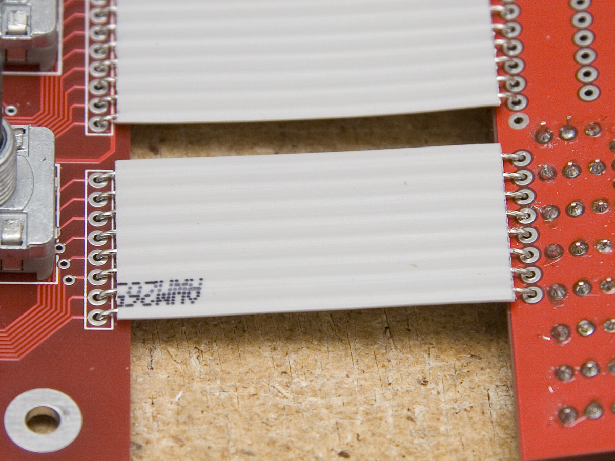
Sorry to hear of your troubles with the cabling... I should have done a better job of explaining my process, with photos... alas too many things to do and not enough time. The ribbon cable I use is tough stuff... the insulation is quite stiff and the wires are thick and practically solid, as it appears like they've been dipped in solder before being put in the ribbon. As such, you need to pre-bend them 90 degrees and solder them flat. I've attached a picture of how I did it... this is TK's box but I did the same technique on my original MB-6582 and that's been opened and closed many times after I finished it!
-
J1 is the DIN/DOUT connection to a Core, i.e. it is 1:1 with J8/J9 J2 is the DIN/DOUT connection to other control surface elements, i.e. the end of the DIN/DOUT chain. J3 is optional Beat LED connection (if not mounting LED to PCB) J4/J5 is where you connect the datawheel encoder pins to the PCB using wires (J5 optional, for encoders with switch).
-
MB-6582 Ventilation & Combined Analog Input and Feedback
Wilba replied to Syntax's topic in MIDIbox SID
fussylizard: that's perfect. Syntax: yes, those pots will then attenuate the audio in, the same way they attenuate the SID output when using feedback. -
http://media.digikey.com/pdf/Data%20Sheets/Optrex%20PDFs/DMC-40267%20Series%20Drawing.pdf http://media.digikey.com/pdf/Data%20Sheets/Optrex%20PDFs/DMC-40267NY-LY.pdf While every reasonable effort is made to ensure that the information provided is accurate, no guarantees for the currency or accuracy of information are made. Information is provided 'as is'. It is provided without any representation or endorsement made and without warranty of any kind, whether express or implied, including but not limited to the implied warranties of satisfactory quality, fitness for a particular purpose, non-infringement, compatibility, security and accuracy. In no event will Wilba be liable for any loss or damage including, without limitation, indirect or consequential loss or damage, or any loss or damages whatsoever arising from use or loss of use of, data or profits arising out of or in connection with the use of this information. These Terms and Conditions shall be covered by and construed in accordance with the laws of MIDIbox. Any dispute arising under these Terms and Conditions shall be subject to the exclusive jurisdiction of the courts of MIDIbox.
-
40x2 Green-on-Black Optrex Displays - ORDERING INSTRUCTIONS
Wilba replied to fussylizard's topic in Bulk Orders
@fussylizard: yes, great packing, now I have enough bubble wrap for a batch of sammichSID kits ;)