Wilba
-
Posts
3,310 -
Joined
-
Last visited
-
Days Won
2
Content Type
Profiles
Forums
Blogs
Gallery
Everything posted by Wilba
-
LOL I already have a CZ-1... and a CZ-1000 I need to sell.
-
.

-
This is as close as you're gonna get to a pre-built MIDIbox SID: http://www.midibox.org/dokuwiki/sammichsid It's at least pre-designed, pre-planned, pre-packaged, and simple to put together by the most newbiest of newbies. Just add solder.
-
Thanks! Next question: do I want one? :)
-
I don't know what it is... but it looks interesting!

-
Batch #1 was posted yesterday... hooray! The build guide is finished, but there is always room for improvement, so please give me feedback. If you have problems, it might be a good idea to start a new topic called "sammichSID Troubleshooting" in the Troubleshooting forum and everyone posts in the one topic. I can always split the topic if it gets too busy. You can find the build guide here: http://www.midibox.org/dokuwiki/sammichsid Have a read now while you await your kit, you might want to acquire some things before it arrives, like acrylic paint, brush, heatsinking compound, solder... :thumbsup:
-
Don't be silly... the "Buy me a beer" link is a joke :w00t:
-
Yes, these changes are specific to MIDIbox SID usage so they were not incorporated into the Core PCB. The resistor can be connected to any "Vd" or +5V connection, it doesn't have to be from J2. Similarly, the diode and resistor can connect to the PIC pins instead of the J15 pins which those pins connect to. So you can put the diode and resistor under the PIC instead.
-
Yes this is the default way of switching between matrix modes if you don't use a matrix mode button (I added that for MB-6582).
-
No, the LED matrix there is very repetitious... http://www.mb6582.org/plans/MB-6582_CS_PCB_R2_Color.pdf I would suggest taking out all the 74HC595 and testing each LED individually by supplying +5V to R48-R55 (the end closes to IC, so power goes through the resistor) and supplying ground to JD8 D0-D7 (i.e. the LED matrix columns). If you can get LEDs in those rows to light up then the problem is with the shift registers (74HC595 ICs). If the problem remains, then you'll need to do continuity tests and work out if those tracks are broken somewhere, or shorting with something else. I did notice your status update says "well, the heatsink I used was too tall and shorted out my CS... lol" so maybe it's related? Explain what happened there, and it might explain why five rows of LEDs don't work. BTW you probably should not assume the LEDs should work until you test every one individually with +5V->220R->LED->Gnd
-
I suspect yes, because if you were running the one specific to MB-6582 then you wouldn't be asking this question: BTW the MB-6582 wiki page had a link to this post/test app but it was broken since the forum change. I really should host that app somewhere else, or at least add another asm/hex to the default one :whistle:
-
From the album: Wilba
Very hard to take a good photo of this nice true green LCD... but it looks something like this:© © 2009 Jason Williams
-
Maybe you're having the same problems I had: The length of cable between the Core and the OPL3 makes a difference. Retest with the testtone app so you take MIDI issues out of the equation and can prove the OPL3 is working fine.
-
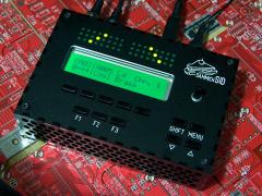
Awesome work! I love how you've stacked everything under the PCB... nicely done.
-
And something for the Germans (and I suppose other Europeans who can buy from Reichelt.de): http://www.reichelt.de/?;ARTICLE=81932; Stecker-Netzgerät, stabilisiert, 1400mA According to my German translator (nILS), this is regulated, multi-voltage and not switchmode. 1400mA is overkill for sammichSID, but it's regulated so it doesn't matter. There's probably another one from Reichelt with lower current rating... German speakers are welcome to post links to alternatives!
-
People have been asking me what power supply/walwart to buy... the specs are in the doco, but I thought I'd pass on a link to what I think is a pretty good one and a good price too (only for USA though): http://www.allelectronics.com/make-a-store/item/PS-1251/12-VDC-500-MA-REGULATED-POWER-SUPPLY/-/1.html Regulated 12 vdc 500 ma regulated wall transformer. Ideal for 1 or 2 CCTV cameras or any device requiring a regulated output. 2.1mm co-ax plug, center positive. UL. Things to note: It's described as a "wall transformer" so I can only assume it's a transformer and not a switchmode power supply. Regulated 12V DC is required for 6581, but it's also nice to have for 8580R5/6582A even though the sammichSID could use AC or unregulated DC. Regulated means that the voltage into the 9V regulator in the sammichSID is going to be constant at any load. An unregulated 12V supply actually can be higher than 12V and only drop down to 12V under its rated load. That means the poor 9V regulator in the sammichSID gets hotter than it needs to be. It's also got the right plug and the right polarity for using it to directly power 6581 SIDs with 12V. If anyone is adventurous and buys one now to see if it's definitely not switchmode and perfect for sammichSID, then please post your experience here and give it a recommendation.
-
sammichSID Production Update Ponoko have officially disappointed me... they were supposed to be totally ready to start making my order for 20 cases about 7 days ago (i.e. have material ready and have already waited in the queue) but they err... umm... ahh... forgot. So I have been assured they'll be made on Monday and I'll have them next week. So maybe next Friday (20th Nov) I can actually post batch #1. Whee! Batch #2 pre-orders have been requested to send order confirmations. Some people are still not replying to that email. I may have to swap them with batch #3 pre-orders. If I told you that you were in batch #3 or #4 and you read this (and are keen to jump the queue), send me an email and I'll move you up the queue if possible. (Nagging me in this thread will not work). Also... I needed to buy some T-shirts and send one to nILS... so in case anyone else is also crazy enough to wear one (and wants to make me LMAO), you can haz one too! ;) (btw there are multiple background colour and style options for each colour of print.) Click the image!
-
13 PCBs reached. No more orders please.
-
I am arranging for someone in the US to distribute this 2nd mini-bulk order of PCBs and some of the parts. This will work out cheaper for everyone. Please note this is still only for "bleeding edge prototypers" - people will have to make their own case and get their own panels made by Schaeffer or Front Panel Express (or DIY if possible).
-
Due to incessant nagging, I will run another very, very small bulk order for PCBs. Maximum of 10 places. I will be nice and pack some Re'an knobs too, but everything else is easily purchasable from Digikey, Mouser or ALBS.de so someone else can manage that. I would REALLY love to just send a batch of 10 PCBs to someone else and let them split it out... but I doubt anyone is willing to volunteer. I guess the PCBs might cost 35 AUD each, but I don't really know until I get a quote. If you are interested, email me at Jason.S.Williams@gmail.com 13 PCBs reached. No more orders please.
-
There is nothing special about the wiring... "user defined" buttons are wired the same as any other. Everything is configured in the firmware, so you can connect buttons and encoders to whichever DIN module pins you like (except encoders must be on DIN pin pairs like D0+D1, D2+D3, etc). So basically design the arrangement you like, the MB-6582 base PCB has five DIN modules and you won't need a switch matrix so this means up to 40 switches, one encoder needs two pins so let's say you use 6 encoders, that's 12 pins, leaving you with 28 switches. Similarly, there are three DOUT modules so you can easily drive 24 LEDs without a LED matrix, or up to 128 with a LED matrix. If you use more than 16, and need to use the 3rd DOUT module (the one with transistors under it), then you'll need to change the resistor/transistor with just a resistor and bridge the transistor pads. Very easy to do, just letting you know not to stuff the resistors/transistors there until you design the CS. Optimal CS between minimal and full? Hard to say... but I would think a 2x40 LCD with 10 select switches underneath would be good. Definitely would need SID 1,2,3,4 buttons/LEDs to control the four SID engines on the MB-6582 (another reason why sammichSID CS is not suitable - no SID 1,2,3,4 buttons!). Add Shift, Menu, Up/Down buttons. Add a SID L/R button + two LEDs (or dedicated SID L + SID R buttons!). A Play button would be ideal if you want to start the bassline sequencer without external MIDI input. That would still leave quite a few spare DIN inputs for "user defined" buttons should you want them. Buttons to jump to commonly used pages (like Osc, Env, LFO, Filter) could be good. For encoders, I suggest the menu encoder and five encoders underneath the LCD for the "knobs" parameter layer that would let you control the "custom" parameters per patch. Ideal for bassline mode. Each patch can have its own set of "knobs", each knob can tweak one or more parameters depending on how you configure the patch. So if you are going to add a few encoders to a mimimal CS, then making them control the "knobs" layer is more useful than any other. If you have room, you could add two more encoders just for filter cutoff and resonance. If 2x40 LCD is too big for your needs, consider using a 4x20 LCD (TK has added some nice bling to the top/bottom rows on this display, so it looks cooler than a 2x20 LCD for only slightly more space).
-
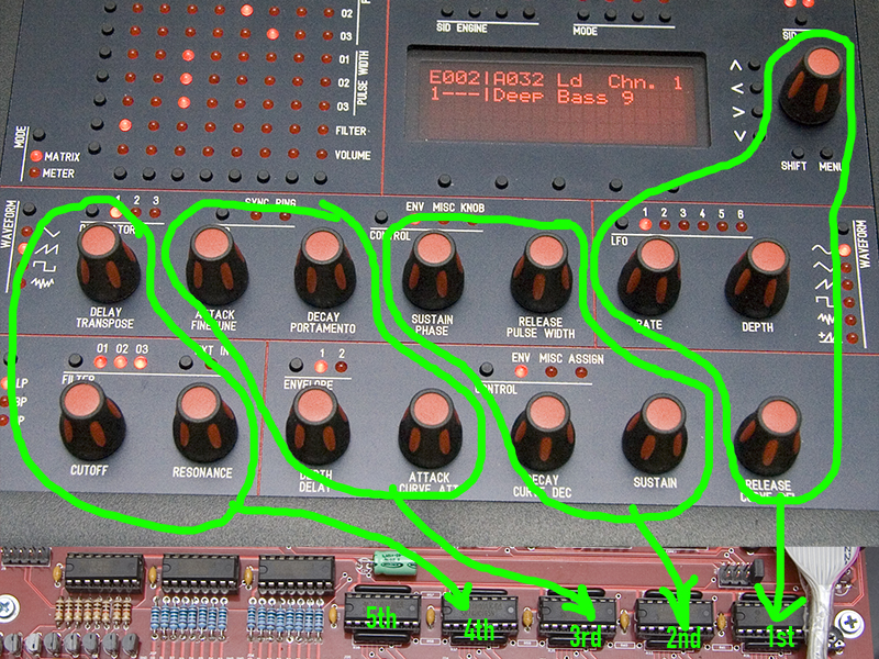
Here is a picture to help explain things:
-
There's no wiring diagram for the encoders, as I didn't think it would ever be required. However, what you are describing suggests that there is something wrong in the DIN modules. At the bottom of the base PCB are 5 DIN modules aka. 74HC165 shift registers. http://www.mb6582.org/plans/MB-6582_Base_PCB_R2_Color.pdf The "chain" starts at the right, near the master PIC. The first four on the chain (right to left) are for encoders, the fifth is for switches. So if only some encoders work and no switches, I think something is wrong in this chain. http://www.mb6582.org/plans/MB-6582_CS_PCB_R2_Color.pdf If you follow the tracks on the CS PCB, you'll notice the encoders that do not work all are connected to the 3rd and 4th (right to left) shift registers and the switches are connected to the 5th (right to left). So... either the 3rd IC is not working, or there's a short or break in the track around this IC. A break in the chain causes all controls further down the chain to not work. I suggest marking each IC with a pencil so you know where you have them placed now.... ie. 1st to 5th. Then you can swap them to prove if they are all working (i.e. test each one in the 1st slot, far right, and test menu encoder.) Hopefully it is something simple like a dead IC or perhaps a bad solder joint (no power to 3rd IC, bad solder joint on the track from 3rd to 2nd IC).
-
Can you guys please update the MB-6582 wiki with pics and links to the Mouser offerings? :)