Wilba
-
Posts
3,310 -
Joined
-
Last visited
-
Days Won
2
Content Type
Profiles
Forums
Blogs
Gallery
Everything posted by Wilba
-
Hey drboom... I know another Aussie who might want all this right now... it sorta would be nice if you pass this onto another Aussie. I'll get him to PM you.
-
Another good site to explain PSUs: http://www.kpsec.freeuk.com/powersup.htm
-
I think the LED was still getting too much current. I've done some more tests with this display and I think R4 needs to be more like 80K to limit LED current to 25mA. With around 47K the LED was probably getting 40mA-50mA which will eventually burn out a LED over time. I'm sorry I suggested the wrong value... I was using 47K myself thinking it was OK, but a real test with a current meter proves this resistor is too small a value. I have one of these displays with low-power amber LED backlight if you're interested, I can sell it to you VERY cheap. The LED can be replaced with another colour LED, if you prefer white, for example.
-
Actually I should pass on these... other people need SIDs, and I have plenty... I just wanted to collect some more 8580 pulls. I'll take them if no one else wants them.
-
It was FUD - I see no suspicious markings, but the response was insulting. I'm guilty of FUD myself (maybe justified) in that other SID sale - those really were remarked. The 6582A's are clearly mine :) I'll take the lot for €120.
-
I kill you filthy (I bet no one will get that connection) (I bet a beer to the first person who CAN get that connection)
-
Don't try to run a keyboard controller on the master PIC of the MB-SID (i.e. on the MB-6582 PCB). The MB-SID firmware takes up nearly all the flash memory, RAM and processor cycles - it's barely coping now with a control surface! It is much better to use a separate Core/DIN modules for the keyboard controller. It's also a LOT of work to get that going, even more if you want key velocity, so the easier option is to use an existing keyboard controller (i.e. a commercial one) as other people suggest. But if you have your heart set on a specific keyboard, keep going, but make that project sort of independent - i.e. get it going as a generic MIDI keyboard outputting on channel 1... then connect that to the MB-6582 base, perhaps through some kind of switch or a loopback MIDI cable so you have the option of keyboard or external MIDI control.
-
Bulk Order #3 of SoundWell rotary encoders **SPARE BOX OF 96**
Wilba replied to Wilba's topic in Bulk Orders
None left sorry. -
Gloss Red and Gloss Black MB-6582 panel sets back in stock : )
Wilba replied to julianf's topic in Fleamarket
My general feeling is... if people have a CNC machine (aka. lucky bastards) are willing to make panels for other MIDIbox builders, I am 100% for it... so long as their offers don't interfere with a currently run bulk order etc. I'm not sure but I think Doug Wellington may be approaching readiness to supply panels but someone like you offering a small quantity for approximately the same price (or higher) is not going to affect his "bulk order".... i.e. I don't think he's going to be overstocked with materials or make a loss etc. One other thing, you should demonstrate what you can make, with good hi-res photos. If you can do (paint filled?) engraving like Schaeffer/FPE then show it... if you can source 1.5mm thick black anodized aluminium... etc. Paint filled isn't that important, I'm sure people can DIY that if you're beating Schaeffer/FPE on price. Can you also do panels 17"-19" wide? ;) Can you do blind threaded M3 holes on the reverse side?? ;) -
I just added text to the wiki:
-
Plan B would be: find someone with a CNC router who can cut clear acrylic.... hmmm... *hint* :)
-
Note the FPE price is because it's got a routed edge so it fits the cavity and thus will be flush on both sides. Since I did the design, I've discovered it's possible to just get 3mm clear acrylic laser cut a lot cheaper... alternately, you could get any scrap of 2mm-3mm clear acrylic or perspex and cut it roughly to fit the cavity at the back, and it would be held in place by the LCD. I will be doing orders from Ponoko soon-ish.... I will be getting some laser cut 3mm transparent acrylic for another project... I'm sure I will have room on the panel for some LCD windows (or do another panel). Now THAT would be cheap, and cheap to post out later too (no need to hold up the bulk order). Or maybe one of you Americans can run a generic "rectangular piece of clear acrylic" bulk order (sell MB-6582's 40x2-sized and MB-SEQ 2x40-sized windows)... (I suggest it cos there's a Ponoko node in San Francisco and NZ so it's cheaper shipping of the order).
-
BTW PCBs for the "bleeding edge prototypers" have arrived. POIDH? GTFO!
-
One other thing... screw length should be long enough so it passes through the PCB mount holes, thus allowing you to use the corner screws to align the PCB to the panel for the spacer gluing stage. Don't get screws longer than 25mm though.
-
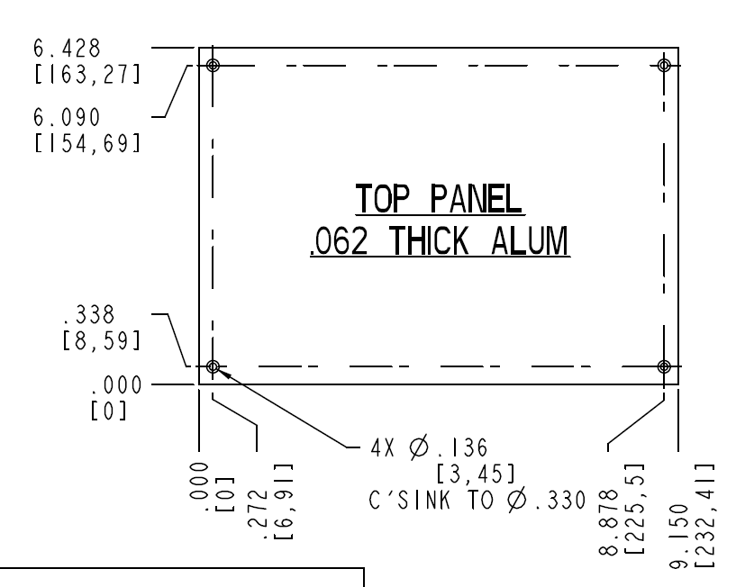
I admit that glued (JB-Weld) counter-sunk screws are a weak point of the design, as other builders have reported. Mine held up quite well until recently when one lifted. The spacers are held on much better. Note that it's the spacers that hold the PCB to the panel, the corner screws only hold the panel to the case, so they are what receive most of the stress of opening/closing the case, much more than the 23 spacers, that stress is so distributed that they'll never break. So aesthetics aside, there's no reason to not put holes (pref. counter-sunk) in the corners. You will need to make the hole match whatever screw you're using, preferably M3, choose your countersink angle/depth to suit the screw... and place them in the right place. Refer to the PT-10 drawing PDF for exact placement... conveniently the mount holes are symmetric, so even though the FPD file has the origin at top-left, you can use the same coordinates as the diagram (see attachment).
-
Those pads are fat at both ends... splitting the wires and desoldering isn't that painful and the chances of lifting a pad are small. I used fairly stiff 0.1" ribbon cable but made sure to pre-bend the wires thus the solder joint isn't stressed. See here. I've opened and closed my MB-6582 at least a hundred times since and had no problems. Right angle connectors are good though, I just didn't want to make 132 crimp pins ;) plus they're impossible to get locally so I treasure the gold plated ones SmashTV sent me.
-
Does solving your other problem also solve the encoder problem completely?
-
LEDs do not light up via LED test program, but do manually
Wilba replied to m00dawg's topic in MIDIbox SID
Good to hear you got things working! -
This effect does happen if you connect an encoder incorrectly (i.e. it has happened to me when I got the pinout wrong and pins 1 and 3 were swapped).... in this case, it's not likely since you probably used the right part and the PCB suits this part. If you manually removed the detent, then perhaps one of the contacts was moved so it's not making contact anymore. Another possibility is one pin is always grounded. On the MB-6582, the right pin (pin 3) should be grounded... however there is an alternate set of pads with a different pinout underneath the intended encoder (STEC16B, Soundwell 16mm, "Voti" encoders)... check if those pads are shorted... it could also be a short between pin 1 and 2. What you can also do is test connectivity between pin 1 and pin 3 (ground)... pref. with a beeping multimeter mode... it should beep while the encoder is being rotated between detents and not beep when it's stopped on a detent. Repeat test between pin 2 and pin 3. You might want to check with a good encoder so you know you're testing correctly. You could also do this test on the left two pins of JD2 (or where they connect to the CS PCB). It's also possible but unlikely that the short is somewhere else along the tracks... like where they pass close to the spacer mount between 5th and 6th encoders on the bottom row.
-
LEDs do not light up via LED test program, but do manually
Wilba replied to m00dawg's topic in MIDIbox SID
Try and identify if the fault is with the transistor not sinking, or a break after the transistor (i.e. through JD8 pin, through the cable, in tracks on the CS PCB). So... LED matrix test again, put in U21 and U22, take out U23, apply ground to the collector pin of the transistor (the one at the bottom, which connects directly to JD8). One "column" of LEDs in the mod matrix AND other LEDs should light up. If column 8 lights up, then it's not a fault from JD8 onwards. Could be the transistor. Try 5V at the resistor/U23 junction (i.e. drive the transistor to sink). If that lights up, it's not the transistor, possibly a break/short between that point and the IC socket. BC547 transistors are perhaps the most common transistor on the planet... except for Americans :) If desperate for a quick fix, use 2N3904 (like from your local electronics shop here ;) ) but you need to invert the orientation because the pinout is different to the BC547. That will at least get you going while you wait for a BC547. -
Excellent... I like this colour scheme! Did you choose to use those knobs because you prefer them to the "Waldorf" ones that everyone else uses? I was thinking the blue-ish translucent ones I used on my original MB-6582 would suit better, or maybe the grey or white ones. If you're interested, let me know, I could send you some (I think I have some spare)...
-
LEDs do not light up via LED test program, but do manually
Wilba replied to m00dawg's topic in MIDIbox SID
Referring to the PCB PDF... http://www.mb6582.org/plans/MB-6582_Base_PCB_R2_Color.pdf U22 pin 9 connects to U23 pin 14... i.e. as you're shifting bits into the shift registers, they shift along across this track to the next shift register in the chain, in the direction U21->U22->U23... so the pin 9 of one connects to the pin 14 of the next. now you COULD do something really wacky to test stuff... take out the IC in U22 (the 2nd one) apply 5V to U23 pin 14 (with IC in!)... i.e. you're making this shift register always output high values. test with matrix text... you should see only the mod matrix LEDs light up try applying 5V to U22 pin 9 instead... which connects to U23 pin 14. Should get same results. If not, broken track or bad joint. BTW be careful when testing IC socket pins from the top side, don't push the probe in, this can widen the contacts. -
LEDs do not light up via LED test program, but do manually
Wilba replied to m00dawg's topic in MIDIbox SID
If you ran the SRIO tester and got the right outputs on the last 74HC595.... then that indicates no problem with communication between that 595 and the previous ones, the whole chain is "good" and the PIC is outputting correctly.... which means I'm confused how that can work and the transistor sinking works yet the matrix as a whole doesn't. The problem now seems to be that IC is not really outputting into the transistors, yet the other two are... you could try resoldering all the joints on that socket and see what happens ;) There's one track that connects each 595 with the previous one on the chain. See DOUT schematic or MB-6582 PCB PDF (I forget which pins it is). Check that for continuity BETWEEN THE IC PINS not the pads. I need more thinking time... ;) bbl -
LEDs do not light up via LED test program, but do manually
Wilba replied to m00dawg's topic in MIDIbox SID
Sorry I didn't read all the details of your last post and suggested stuff you have done already. When testing SRIO... did you test high (5V) outputs on the last 74HC595? i.e. DOUT outputs 16-23? Try the LED test again with 5V going into the resistor, as I suggested... i.e. simulate a 5V output from the 74HC595. That will test the transistor (but then if the SRIO test on that 74HC595 passes, it's sort of testing the same thing). SOMETHING is wrong so test everything and work out what's wrong later (don't skip a test and assume anything!) Working encoders just means the first four 74HC165 are working. You need to test if the switches work, in order to test if the current sinking is working as expected. The good news is, you installed all the LEDs the right way ;) -
LEDs do not light up via LED test program, but do manually
Wilba replied to m00dawg's topic in MIDIbox SID
If you remove the last 74HC595 and sink JD8 pins and LEDs light up (i.e. from the other two 595s working) then there probably is no problems like shorts or breaks on the CS. One bad transistor can only mess up those LEDs on that "column". I suggest swapping 74HC595 to see if they all are working properly. Label them and put the last one (above the transistors) into one of the other slots and try the "grounding JD8" test again. If they're all working, then perhaps there's a problem with the last 74HC595's socket... ie. not getting 5V/gnd, no connection to the SC/RC or the previous 74HC595 (i.e. how they are "chained"), etc. You can also try an extension of the "grounding JD8" test you've done... take out the 74HC595 and instead of grounding JD8 pins, apply 5V directly to the 1K resistor where it connects to the IC pin... i.e. test both putting 5V into the socket pin and also to the resistor pin FURTHEST from the transistor, not the one NEAREST (you don't want to put 5V directly into the transistor pin!). This will test if the transistors are OK and also test if the socket pins are OK but they should be IMHO... the problem now is probably the IC is dead or a connection to it is faulty.