
Phattline
-
Posts
456 -
Joined
-
Last visited
Content Type
Profiles
Forums
Blogs
Gallery
Everything posted by Phattline
-
adding 16 permanents independants track mute buttons on SEQV3
Phattline replied to matoz's topic in MIDIbox SEQ
that would be also cool for the mb808 ....but I also have no idea...I have still problems by programm a video recorder, but, hey when you have the code--- I copy it from you ;D hehe -
I buid 300 from this (but with the standart cover....not sooooobig) I have them in others projects too.... they are sooooo cooooooooooooool! (mechanical) But maybe others would be better for the workflow...(just a little promille....) Others which Cover is at all illuminatet..... so you have a User interface,which is mor clear---you see a light- you push it- the sound comes....and with the black buttons you have a small red light, and if you press it, nothing happens ;D "oh I must push a little bit under...." but that is all relativ after a time.... so take the black ones... they are good!
-
;D uuuuuups :D
-
I thougt, I fully stuff the Controll sourface ©, so I have for Future, things open...maybe add some oszialltores, pwm and so on....hehe... I thougt like this, instead of 4xSID mainboard, I use the 303board, and a Stereo-SID board and a TR909 Kick board, controlled with one Sourface.... but all on seperate modules...so If somebody want to build a 303standalone, Device, He could integrate it in his already existing SID.... And I use a 19" RACK for Liveacting...so I have enough place for all of it.... And with the SID integratet....I still get it thru the 303 filter ;D.....So I want to make it more modular....we will see we will see, but maybe, I, will get a singel SID on the 303 pcb (200x260mm pcb double layerd...) there is still a little bit of place
-
Phatline needs: 130 x 3FTL6 UNKNOWN. $1 or so. 130 x S11.16.0 (Clear cylindrical) .40c ;)
-
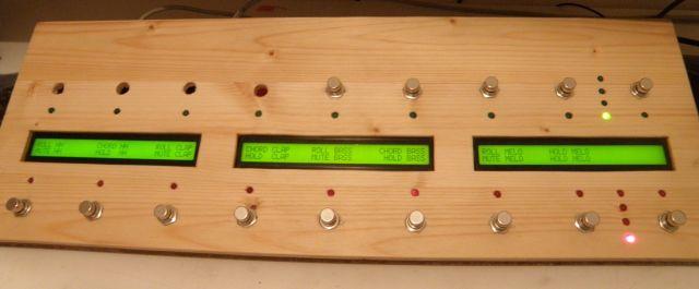
The Plan: MB808 with Trigger-/ACCENT-out without TR-808 analog section The PCB should be single sidet, so I can etch it on my own ;D , and that should cost with chemicals max. 30€ But there are some unclear things now. Questions: Do I need Menue Buttons under the LCDs? If I use the Midibox-Clockbox, for Start and Stop my Equipment, Do I need also on the MB808 this buttons (I actually left it out) If the MB808 is MIDICLOCK-SLAVE (clockbox is Master) The 3Digit 7segment LED-Display shows also the BPM?[/liIs it or will it be possible to add a second 16x4 dualmatrix? ;) to have 8times a 16step sequence???? for me in most cases, 8 Instruments is all I use (for drums now) 8), it would be the ultimativ, super trupa phat mega groovy uuuuultra geile Drumsequencer (ok it is now already, but hey ;D ) On the 808 website: there are the Shematics and PCBs in eagle-format, but only in single files... so you have pictures like that, on your screen: www.phatline.at/MB808/Accent.png www.phatline.at/MB808/LED-Trigger.png Should here everybody know what is going on here, should be it DO IT YOURSELF, or have some people paranoia? With this pictures I really cant understand the coherences. no, I know something of electronics... but a technician without a complete shematic, cant work ;) :-\... so if somebody can send me the shematics, pm me...please- thankz! The LED-Trigger is only for the LED??? or is it a ampliefier for the trigger signal? (again the complete shematic is left! If I want trigger out, that are able to trigger Roland Drummachine like the 808 909 or 606, Is this simple use a Doutregister? or Do I need a transistor circuit? to get more then 5V?, And whats about:... ...whats now with the Accent Circuit?... clear me up :P Where is the Accent POT that we have on the most Drummachines? For your info, the Accent Pots, modify the Accent Ammount..from 0 (no accent) to max on the accentet notes TK wrotes: Sorry but why do that that way? ;D If that work as you sayd, do I need expensive AOUT?, or I simple need, two outputs of a DOUT register, one with a resistor one without...and now you have already accentet or non accentet.... why use a AOUT when it isnt "controllable" in fine steps like 0-127 ??? What I didnot understand here? The swing Pot: is a POT (a resistor...) and it is connectet to the Core where? J5 J6? which Pins? 0-5V? The following Pcbs, and its buttons...they are fully stuffed, or is there anything that, comes (maybe in future...) Design for Fully stuffed with 2x 2x40 LCD: The complete pcbs (front and core...) consists of 3 Piece 200x150 PCBs. The complete shematic is ready ;): www.phatline.at/MB808/shematic.png The FRONT-PCB---> I still have a some airwires... but ok, I dont care.. ;) www.phatline.at/MB808/frontpcb.png The MAIN-PCB---> I still have a some airwires... but ok, I dont care.. ;) www.phatline.at/MB808/main808.png If the fully stuffed is to big.... 3,6cm x 20cm is the size of the 4x16 Matrix with DTL switches if you dont know about what I am talking bout...that are these http://www.phatline.at/MB808/pronbuttons.JPG (here 300 and 1 ;D ) Now what do the LCDs exactly? What shows it?....no away with them over the Matrix >:( ;D and then I have still place for all the other buttons next to the Matrix, so it finally it fits in a smaller Rack with less "höheneinheiten" size.... and size/place nobody have ever to much.... ok here the finally front panel for the 2HE (HU) 19" MB808 that I will build overview http://www.phatline.at/MB808/808front-klein.png left-detail http://www.phatline.at/MB808/808-front-klein-links.png right-detail http://www.phatline.at/MB808/808-front-klein-rechts.png how ever there exist a ready routet shematic and eagle pcb... http://www.phatline.at/MB808/808-front-klein-pcb.png The Main PCB: http://www.phatline.at/MB808/808-pic-pcb.png ....not completely autoroutet...i cant wait...heh....and the trigger outs and Accent shematic are missing...because...I CANT FIND ANY DOCUMENTATION ABOUT THIS ( wahhh! wahhhhhh wahhhhhhhhhhhhhhhhh ::) All 4 PCBs can be placed on 2 single sidet PCBs from this, @ 6€ each....= 12€ euro for pcb ;) http://www.reichelt.de/?;ACTION=3;LA=2;GROUP=C911;GROUPID=3368;ARTICLE=33771;START=0;SORT=-artnr;OFFSET=1000;SID=31nnv@LKwQAR8AAGO9Hu47679e5705e3a39ea54a88904699bb8db A Frontpanel in DXF format will come early. A Case in DXF format will come also then ;) like I did bevor on a other project...: open for Ideas---mike
-
jop here is my frontpanel http://img293.imageshack.us/my.php?image=303frontmq0.png and the pcb for it http://img145.imageshack.us/my.php?image=303frontpcbrr5.png on the analog section, I am Still working...
-
ahh ok- thankz
-
Hi. I have masses of midifiles...made with ableton... a lot of snippets from 16 to 64 steps... in normal midiformat...since I dont like my laptop on gigs...it would be cool to get this midifiles in the SeqV3. So is it possible, or planned?
-
Hmm there is already a smdchip on there....(AOUT NG-module!) So if people cannot solder smd, they cant do the project....because aout is a must. And if they can do, they also can do 3 more chips ;) . but it is easy to change the Devices, so for me it will be a smd, and for others- others---thats a thing of 15 minutes...since my layout is autoroutet ;) .
-
When I summ the outputs. The Outputs will always have the same Volume??? ---So If I sum Output A&B=1dB and A alone is also 1db? If I have Volumechanges, I have to adjust the output in the livact, and thats not good! (I know that) Ok with IC12 (that should be a switch that opens the contact if it gets a Switch Signal!) I just Switchoff to the Output Resistor (the 200K ones) a paralle Resistor ( a trimmer), and that should lower the volume, if I switch on a Switch on IC9! So my Idea was, to get, alwasy constant (or nearly constant volume outputs) Why not? (answer because there is still place ;D) I dont having problems with SMD parts....I have to drill less Holes, (By PCB Mike you save money ;) ) you have more place to route (on double layerd boards)...
-
;) there is still place for a few tweaks on the pcb...:
-
I am proudly presents my volumeconstant Waveformswitcher&Mixer :P ... if there is a better way to do that---tell me ;) How it should work: If we look at the IC9A & IC9B: IC9 Switch the Waveforms IC12 Switch the Resistors (this SWITCH must be Turn off if it gets Voltage!----which SWTICH can this????) If a Waveform is switched on (input IC9 gets voltage) =>The Resistance of Parallel circuit get high. (The 2nd Resistor of the parallelcircuit is switched off---its now a high OHM serial Resistor!) If a Waveform is switched off (input IC9 gets no voltage) => The Resistance of the Parallel circuit get low (its now a parallel circuit, the Resistance is setuped with the Trim-pot)
-
cool-thankz for the picture! In the XOXBOX Forum, they said me, If I want to use one OPamp for two operations, I should take the tlv2372....I bevore hat taken a AN6562, but they said "it dont go @ the top of his rails" (i understand the technical english not very much ;) ) or something like that, I dont know waht that meens, but the AN6562 is not the right OP-amp for this operation ( to take the ouput of the op amp and get it into the negativ input---and that with the 2 inline op amps in the chip....) But for summing the differnt sources I should take a tl071? ---but a question, why I do nee the here a summing amp? (I cant mix the 4 sources---because the SAW and SQARE of one and the same VCO cant be Mix togehter, that because, the OSC will be coloured ---because of its shematic....why exactly---I dont know- but I have to buffer them---thats what I know!)
-
done ;) the whole topic is cleared up (from my side) 8) Here the pinout of the 4066
-
I now already use 2 buffer amps, to mix the VCO1 and the VCO2 (since I build two TB303 VCOs) I thougt I will mix them with CV like on this shematic: Signal A is the switched VCO1 with SAW or WAVE...Signal B is the same only for VCO2 It is a cool Idea to switch the seperatly, but then I must have 2 more puffer amps.... But a qestion If I use 4 switches and 4 Buffer amps, where I can mix them.... it is the same shematic wright? only with 4 buffer amps...in thwo groups, yes of course Signal A=switchabel SAW and SQAURE...The REason I cant fade them, is, that I have only 8CVs and they are still to "unzureichend" "insuffizient" :-[
-
MB-SEQ V3/V4 Control Surface PCB and matching case
Phattline replied to Wilba's topic in MIDIbox SEQ
Oh dam I´m really interestet for 2 Kits, comes what comes :o I will be happy ;D -
cool thankz. that is good that I only need one part(and its not mechanical--yes!) A qestion to this, I should use the 4016? or I can use both(the 4066)? And a 4016 can only switch one? or more?---The reason why I ask this: The SAW and SQARE Wave OSCillators cannot be mixed (without audiobuffering....and with two VCOs that would be 2x2=4 audiobuffers-to much PCB-place would be needet), so I need a toogle switch.... If this not exist I must take 2 but I am happier with one ;) To the supply, I will take the orginal. But the Rectifier Diodes will be stronger, because, I also drive there a 78S12 79S12 78S09 78S05 ..... ;D A fiew persons meant that when the 12V stage and the 5.333V stage are in the same OP-amp- the Temperatur drive whould be eliminatet, so if it drives, it drives alwasys together... or so...
-
Why 4CVs for a Filter ??? The switch is to select sqare- or saw-wave. I want to do this via the Midibox, to store the setting for presets...but ok thats future sound...for this I must program a little I think... and I cant ::)...but there is already a function in the sid for this... the waveform selecter switch... The Voltages are: 12V and 8V ;) I switch audio, but of course powerfull audio ;D Hm the use who made the filter PCB- took a relais for his bypass-switch. With a Relais its easier to do, since you only need a dout-out-and nothing else. The sound will be untouched!http://parts.digikey.de/1/1/122391-relay-smt-dpdt-1a-5v-gullwing-g6k-2f-y-dc5.html With that shematic: http://www.uni-bonn.de/~uzs159/switching.png You have a CMOS or whatever switch, With that shematic, the distortion or the colouring of the sound will be hard limmetet. They say: if you switch the whole current thru the cmos, the sound will coloured! So the need a big circuit for one switch: :o of course with the Railais I have the orginal sound! But its mechanical ::) , one error change more >:( , but ok, its much easier, and cleaner.
-
no no no you dont understand me ;)....I am still talking about CV and the TB303....so: Is there any preset setting in the SID what says: CV1 from the AOUT-MODULE =Cuttofff----> The SID application has already a preset setting for the encoders and the DIN modules for it ;) ----> is there a preset setting for the AOUT in the MB-SID Firmware???? ;) I know that I need the aout module ::) The Tread titel is named CVTB303 VCOworking? because- my first question was, can handle the MB the current that a 303 needs? I think yes. But I have to CV the whole 303, except from the Envelope---that will do independet for VCA and VCF the SID envelopes and LFOs ;D No my fealure... I meant of course the DOUT modle. So I was talkin about the little small DIP-form- devices---the digital switches, that are switching, if they get a current---for exemple bya DOUT module. Of course I know what momentary switches I take. Thankz I will search
-
more question about the midibox SID-CV: Is there any preset setting in the SID what says: CV1=Cutoff CV2=Resonance usw....??? Or it doesent matter, because, it easy to edit in the SID-Application???? When I use digital switches (dout modul remotes a switch, and the switch ---switch audio)(8 are supportet?) which switch could that be? What Voltage Controlled Resistor can I take? (aviable in the EU- germany-austria...) and has anybody have a shematic for that--thankz
-
MB-SEQ V3/V4 Control Surface PCB and matching case
Phattline replied to Wilba's topic in MIDIbox SEQ
Yes Button Matrix.... ;D ;D I´m also interestet Rackmount/Desktop: Maybe A design which does both? ---removable Rackmounts ;). And a variable outboard- and with holes for it for both situations ;) --- If somebody has somebody how can cut Iron via laser ... thats would then be no big deal...a quick autocad drawing and its done ;) ( a design like a post-package, cut the forms, the rest is bending and mounting....but hey only an Idea) -
ahhh ok- :D thankz...no I have it, I switched on all layers! ripped off all routings- autroute....and there is it.. ;D ...
-
Yeah add me please... now I have a friend with payball ;)
-
(hopefully the rigt forum---the NG is a user Project-right?) OK here is the image of the eagle PCB: whats about C5 and LED1 what is for? and why are they open? And where is the eagle shematic file....I need this because, I integrate the circuit in my 303 shematic... and when I add this boardfile to my board- I loose my back/forward compatibility ...and thats >:( thats hurts. Anyone the eagle shem??? And the Boardfile seems not be from eagle generatet? Since I cant move the parts, it looks like a Xref, with painting on it in Eagle..... Any Ideas?