
Phattline
-
Posts
456 -
Joined
-
Last visited
Content Type
Profiles
Forums
Blogs
Gallery
Everything posted by Phattline
-
not really, hm, I already was searching on google, but I dont found somthing with the words: passiv line filter schematic There are quite much schematics for MHz ciruits, quite much for active filters with op amps and they are all big ciruits- I need schematic for the "nF" for the low Frequenzy, a small circuit and it must be analog because my Studio is analog. Of course it would be cool when i can chance the frequenzy´s by using a pot. Anybody a Idea for a small compact circuit, and a Term for it. It should be passiv, maybe a OPAmp so that I always have the same impedance-resistance- but all other parts should be Capacitor Resistor and Coil no Transistor or IC....because it should be built 16times ;D Help needet
-
Hi, I am on the way, to make my studio mobil - in two small racks - I own already a Mixer but this thing is to big! So I was searching in the Internet on different Music stores for a small 16 chanal Rackmixer, - and I found it - but the mixers have no EQ or have a simple two way EQ. And trust me I am addictet to 3 Band EQ or parametric meedles....so I need per Instrument a different Frequenzy...And After I calibrate the EQ one time, I dont need them to calibrate it no more....ok I think I need 16 severell passive line Filters, I dont need a amplifiing I only need Reduction. I need a simple standart circuit, and with chanching severell Resistors or caps i can calibrate it. The importent frequenzys are: a 75 HZ 18db/oct cut of circuit - that meens all frequenzys under 75 hz are killed. -//- the same but with 12 KHz - that meens all frequenzys over 12 Khz are killed. and circuit for reduction severall frequenzys by replacing Resistors or caps Anyone has done this bevore, or has a cool circuit,- post it please- greets Mike
-
I took a very small Screw driver, I put it beteewn The YAC Body and the leg, and then I heat the leg short and at the same time I pick up the screw driver- now the Legs are twistet but free, and it works- greets van da sids phat _I_I_I_I_I_I_I_I_ I.....................I I.....................I I.....................I I____________I ..I..I..I.I..I..I..I..I.. _I_I_I_I_I_I_I_I_ I.....................I I.....................I I.....................I I____________I.........._____ ..I..I..I.I..I..I..I.-I-----------I_____I.. Screwdriver ..................../\................I ....................I.................\/... Pull it in this way........ Soldering Iron And now go the OPL3 chip and make one pin the next pin mak on the yac.....and so on
-
Danke schön. Habts ihr eine Idee wer solche Resonator verkauft, und das für unter 50 Euro nach Austria? greets von de sids
-
I ok I understand the number below market the date - ahhh my CSG is built in 1992, and my MOS are built in 1988/89 thanx for this cool link
-
Ja danke erstmal, ja das mit dem maxim teil, hab ich am eigenen leib erfahren müssen, keiner hatte den - conrad nicht reichelt nicht lokaler händler nicht, naja und den resonator hätt ich bei reichelt bekommen -aber nach Austria liefert der erst ab 50 euro.. Also versteh ich das richtig : Ich nehm also einen 22 pf Kerko schließ in an masse den anderen pin an den quarz - die andere hälfte des Resonators auf +5V ? und wo kommt dann das Rechtecksignal raus - vermutlich auf der seite des Quarzes wo der Kerko ist??? +5V | | ---- ---- (Quarz 14,318 MHz) |------------(Rechteck signal - auf OPL3 chip) | ---- ---- (Kondensator 15 -22 pF) | | __ Masse
-
Ich steh grad vor einem Problem, hab keinen Resonator zur hand für das opl3 modul, also 14,318 Mhz. Wie mach ich aus einem Quarz einen resonator, was ich dafür brauch weis ich: 22pf Kerko und an 14,318 Mhz Quarz Schaltung? Pining von der Schaltung (also welcher pin gehört in die platine....) einen max6007b wo bekomm ich den her? -also nur nebenbei. sers phat
-
Hi After I take two SIDS from 2 C64 C ´s I Get MOS 8580R5 2888 25 MOS 8580R5 0589 25 I was still wondering because all other 8580 I get where CSG8580R5 5092 25 - from Commodore,,, hm is there any different, optic: the body is darker and the type on it has more contrast.... greets phat
-
Jo hardware scheint in ordnung zu sein, stürz mich jetzt mal über die mk_syx.zip- thanx phat
-
Re: Keyboard zones confusion (was: SID as a drum machine?)
Phattline replied to Phattline's topic in MIDIbox SID
I dont understand this, when I go to configuration menu, i filter the notes - right? yea Ok then I call the patch, KICK 85`, i filter the notes that only C1 came thru, ? yea Ok I go to slave1 call the patch, Snare 85`, i filter the notes that only E-1 came thru, ? no this isn´t because only the master is filtering Is it right that this note filter is not in function with 16F slavecores? so i have to upgrade? so I understand. Lg phat -
Oh man, thats it, I had always the problem that i must use one midichanal for kick one for snare one for hihats, and then I had only one SID for Lead or Base, But! I was thinking about building a second full stuffed (4 quad) Midibox Sid and take for each instrument one sidmodule, because some drumsound must have 3 oszillator- because the have more punch like for basedrum, with one oscillator you need a compressor to get punchy basdrums, but maybe we can make a simple compressor with a optocopler (in the web there are enough plans about it) or "only " a software for the normal Step C Midibox that splits the incoming midinotes in C-1 D-1 A-1 B-1 or whatever and send it to the master for basedrum to the 1st slave for snare for the 2nd slave for Hi Hat for the 3rd slave for the open hihat or toms or blönks or whatever, and for all this some analog compression, and to get near all time the same loudness, because to get different sounds you will limit or expand in a big way the volume- and thats meens this is not good for liveacting...... lg phat
-
Jetzt hab ich noch ein dinx4 modul draufgehängt, und mit´n Hirschmann Messtrippe mal nach der reihe einen kurzen geschlossen. Es werden alle eingänge hardwaremäßig erkannt man siehts ja an den blinkenden o´s nur, das was ich programmiert hab is es nicht, immernurNotenwerte von 2 register mit c_3 und die letzten 2 Register mit C_4 wenn man die eingänge auf masse schließt erscheint kurz der wert 127... Ich hab schon diverse einstellungen und sysexen probiert von main.sys bis sid.syx- ich kappiers nicht, ich glaub ich werd mich damit abfinden müssen das nix geht, hat das ganze mit den nicht vorhandenen generall purpose buttons zu tun, oder deren einschaltung......no idea... bin wirklich überfragt http://www.ucapps.de/midibox64e/midibox64e_sfb_table.txt- , mit dem kann ich nix anfangen- was soll ich damit machen? mit syxen herumspieln wie meinst das? also ich hab jetzt schon ne menge in den .asm´en herumgespielt- keine änderung das problem is das gleiche,,,,, muss ich vieleicht noch ihrgendwo in einer iotables oder what ever was herumstellen damit diese MB64 funktionen funktionieren ? - sers phat
-
OK wenn ich metaevents (double notes) oder MB64e presets verwende, erscheint nach drücken der taste 1.1 ooooooo 1|CC#[127]o beim loslassen kommt ne null in der klammer, das komische das ist bei jedem meta oder mb64e die gleiche LCD message..... alle anderen wie z.B pichtbend funzen problemlos, ihrgendwie sprechen die mb64e presets nicht an # Lg Mike
-
Was machst du für live musik? techno, electro dßb......
-
Hallo, die Dec/Inc Tasten vom Menü? oder ihrgendeine Taste die du mit INC DEC Group belegt hast. Sorry ich weis nicht was SFB Codes sind, komm selbst eher vond er elektronik seite (hoffentlich hats nix mit elektronik zu tun :-X) Also im vmidibox ist dieses MB64E: Decrement Group with overflow - dings mit metaevent und der metaevent id 16 angegeben. servus mike
-
Servus, gut ich schreib jetzt noch meine hardware hin: 1 Core ein bankstick (kleiner) und ein Dinx4 modul das erste register des DINS is für die Taster reserviert es sind aber nur 6 und 7 angeschlossen die restlichen 3 Register sind mit 12 encodern belegt. hier noch meine main.asm ; MIOS Application ; MIDIbox64E ; ; #ifndef SEPERATE_SETUP_FILE ; Hardware related setup: ; ; Number of connected encoders: 1-64 #define DEFAULT_NUMBER_ENCS 12 ; number of connected encoders ; NOTE: the encoders have to be assigned to the DIN pins in mios_tables.inc ; ; Width of a group - normaly matches with the number of connected encoders, but ; the MB64E_LCD_PrintGroupNumber function in mb64e_bank.inc only supports ; group widths which are a power of two (1, 2, 4, 8, 16, 32, 64) #define DEFAULT_ENCODER_GROUP_WIDTH 16 ; Number of connected buttons ; Allowed values: 1-64 #define DEFAULT_NUMBER_BUTTONS 8 ; number of connected buttons ; ; debounce counter (see the function description of MIOS_SRIO_DebounceSet) ; Use 0 for high-quality buttons, use higher values for low-quality buttons ; NOTE: with a value > 0 the ledrings will flicker on every button movement! #define DEFAULT_SRIO_DEBOUNCE_CTR 1 ; ; ; A difficult decition: define here if you want to store many banks or many patches ; in the (optional) BankStick(s). ; - Bank based (PATCHMODE 0): 8 complete configurations are stored in each BankStick ; - Patch based (PATCHMODE 1): 1 configuration bank and 128 patches are stored in each BankStick #define DEFAULT_PATCHMODE 1 ; ; Chip Select Number of BankStick which should be used: ; -1: allows the MIDIbox to address up to 8 BankSticks (-> 64/8 Banks) ; 0: the MIDIbox addresses only the BankStick with CS=0 (-> 8/1 Banks) ; ... ; 7: the MIDIbox addresses only the BankStick with CS=7 (-> 8/1 Banks) ; all others: don't use any BankStick ; ; * -1 is the most prefered choice, also when only one BankStick is connected. ; * specify a CS number 0...7 when you are using different Applications ; with your MIDIbox in order to assign a dedicated EEPROM to it. ; * specifiy any other number to disable BankStick support at all #define DEFAULT_BANKSTICK_CS 0 ; ; Channel which is used to send a program change event on bank changes ; and to listen for bank change requests ; Allowed values: 1-16 #define DEFAULT_BANK_PRG_CHNG_CHANNEL 1 ; ; Channel which is used to send a program change event on patch changes ; and to listen for patch change requests ; Allowed values: 1-16 #define DEFAULT_PATCH_PRG_CHNG_CHANNEL 1 ; ; here you can change the default device ID #define DEFAULT_DEVICE_ID 0x00 ; ; if this option is enabled (1), the DEFAULT_DEVICE_ID won't be used, but ; it will be automatically derived from the MIOS Device ID instead #define DEFAULT_AUTO_DEVICE_ID 1 ; ; For MIDI activity monitor: define the DOUT pins for the Rx and Tx LED #define DEFAULT_MIDI_MONITOR_ENABLED 0 ; if 1, the Tx/Rx LEDs are enabled #define DEFAULT_MIDI_RX_LED 0x40 ; DOUT SR#9, pin D0 #define DEFAULT_MIDI_TX_LED 0x41 ; DOUT SR#9, pin D1 ; ; --> define the DOUT registers which are connected to the LED rings here: ; --> the shift registers are counted from one here - means: 1 for the first, 2 for the second, etc... ; --> please mark unused ledrings with 0 #define LEDRINGS_SR_ENC1_16_CATHODES_1 0 ; first shift register with cathodes of the first 16 LED rings #define LEDRINGS_SR_ENC1_16_CATHODES_2 0 ; second shift register with cathodes of the first 16 LED rings #define LEDRINGS_SR_ENC1_16_ANODES_1 0 ; first shift register with anodes of the first 16 LED rings #define LEDRINGS_SR_ENC1_16_ANODES_2 0 ; second shift register with anodes of the first 16 LED rings #define LEDRINGS_SR_ENC17_32_CATHODES_1 0 ; first shift register with cathodes of the first 16 LED rings #define LEDRINGS_SR_ENC17_32_CATHODES_2 0 ; second shift register with cathodes of the first 16 LED rings #define LEDRINGS_SR_ENC17_32_ANODES_1 0 ; first shift register with anodes of the first 16 LED rings #define LEDRINGS_SR_ENC17_32_ANODES_2 0 ; second shift register with anodes of the first 16 LED rings #define LEDRINGS_SR_ENC33_48_CATHODES_1 0 ; first shift register with cathodes of the first 16 LED rings #define LEDRINGS_SR_ENC33_48_CATHODES_2 0 ; second shift register with cathodes of the first 16 LED rings #define LEDRINGS_SR_ENC33_48_ANODES_1 0 ; first shift register with anodes of the first 16 LED rings #define LEDRINGS_SR_ENC33_48_ANODES_2 0 ; second shift register with anodes of the first 16 LED rings ; #define LEDRINGS_SR_ENC49_64_CATHODES_1 0 ; first shift register with cathodes of the first 16 LED rings #define LEDRINGS_SR_ENC49_64_CATHODES_2 0 ; second register with cathodes of the first 16 LED rings #define LEDRINGS_SR_ENC49_64_ANODES_1 0 ; first shift register with anodes of the first 16 LED rings #define LEDRINGS_SR_ENC49_64_ANODES_2 0 ; second shift register with anodes of the first 16 LED rings ;; see the documentation of MIOS_ENC_SpeedSet for the purpose of these values #define DEFAULT_ENC_SPEED_NORMAL_MODE MIOS_ENC_SPEED_NORMAL #define DEFAULT_ENC_SPEED_NORMAL_DIV 0 #define DEFAULT_ENC_SPEED_SLOW_MODE MIOS_ENC_SPEED_SLOW #define DEFAULT_ENC_SPEED_SLOW_DIV 6 ; (6: increment on every 7th step) #define DEFAULT_ENC_SPEED_FAST_MODE MIOS_ENC_SPEED_FAST #define DEFAULT_ENC_SPEED_FAST_DIV 2 ; (2: divider = 2^(7-2) = 32) ; This DIN map allows you to customize the MB64E application to different hardwares ; The MB64E dump structure allows the use of up to 64 buttons, they are grouped to 8 buttons per shift register ; Define the used shift registers for the buttons here ; the shift registers are counted from one - means: 1 for the first, 2 for the second, etc... ; mark unused button groups with 0 ;; NOTE: by default, the first two DIN shift registers are used for the encoders #define DEFAULT_DIN_SR_PIN_01_08 1 #define DEFAULT_DIN_SR_PIN_09_16 0 #define DEFAULT_DIN_SR_PIN_17_24 0 #define DEFAULT_DIN_SR_PIN_25_32 0 #define DEFAULT_DIN_SR_PIN_33_40 0 #define DEFAULT_DIN_SR_PIN_41_48 0 #define DEFAULT_DIN_SR_PIN_49_56 0 #define DEFAULT_DIN_SR_PIN_57_64 0 ; ; Datawheel for menu navigation/data entry connected or not? ; A datawheel can replace the left/right buttons! ; if 0: datawheel not connected ; if >= 1: encoder number assigned to datawheel function ; don't forget to check the pins of the datawheel in MIOS_ENC_PIN_TABLE (-> mios_tables.inc or setup_*.asm) ; it has to be connected to pin 4 and 5 by default #define DEFAULT_ENC_DATAWHEEL 0 ; ; DIN pin numbers of menu buttons #if DEFAULT_ENC_DATAWHEEL == 0 #define DEFAULT_DIN_MENU_EXEC 0 ; menu exec button assigned to DIN pin #7 #define DEFAULT_DIN_MENU_RIGHT 0 ; menu right button assigned to DIN pin #6 #define DEFAULT_DIN_MENU_LEFT 0 ; menu left button assigned to DIN pin #5 #define DEFAULT_DIN_MENU_SNAPSHOT 0 ; menu snapshot button assigned to DIN pin #4 #else #define DEFAULT_DIN_MENU_EXEC 0 ; menu exec button assigned to DIN pin #7 #define DEFAULT_DIN_MENU_SNAPSHOT 0 ; menu snapshot button assigned to DIN pin #4 #define DEFAULT_DIN_MENU_RIGHT 0 ; NOT USED - overlayed by datawheel #define DEFAULT_DIN_MENU_LEFT 0 ; NOT USED - overlayed by datawheel #endif ; ; This DOUT map allows you to customize the MB64E application to different hardwares ; The MB64E dump structure allows the use of up to 64 LEDs, they are grouped to 8 LEDs per shift register ; Define the used shift registers for the LEDs here ; the shift registers are counted from one - means: 1 for the first, 2 for the second, etc... ; mark unused LED groups with 0 ;; NOTE: by default, the first four DOUT shift registers are used for the encoders #define DEFAULT_DOUT_SR_PIN_01_08 0 #define DEFAULT_DOUT_SR_PIN_09_16 0 #define DEFAULT_DOUT_SR_PIN_17_24 0 #define DEFAULT_DOUT_SR_PIN_25_32 0 #define DEFAULT_DOUT_SR_PIN_33_40 0 #define DEFAULT_DOUT_SR_PIN_41_48 0 #define DEFAULT_DOUT_SR_PIN_49_56 0 #define DEFAULT_DOUT_SR_PIN_57_64 0 ; ; ; Some menus are providing the possibility to use 16 "general purpose" buttons ; for selecting a parameter - e.g. the Bank Select menu allows to directly change the ; Bank with these buttons. So long as you stay in this menu, the normal function of ; these buttons (triggering MIDI or SFB events) is disabled ; Define the two shift registers which are assigned to this function here: ; 0 disables the GP buttons (not recommented!) #define DEFAULT_GP_DIN_SR0 1 ; first GP DIN shift register assigned to SR#2 #define DEFAULT_GP_DIN_SR1 0 ; second GP DIN shift register assigned to SR#3 ; ; above these buttons LEDs should be mounted to visualize the selected parameter ; (e.g. to visualize the bank which corresponds with the buttons below) ; Define the two shift registers which are assigned to this function here: ; 0 disables the GP LEDs (not recommented!) #define DEFAULT_GP_DOUT_SR0 0 ; first GP DOUT shift register assigned to SR#5 #define DEFAULT_GP_DOUT_SR1 0 ; second GP DOUT shift register assigned to SR#6 ; ; with following settings it is possible to center the screen on 2x20 and 2x40 LCDs ; see also the functional description of MIOS_LCD_YAddressSet ; recommented values: ; 2x16 | 2x20 | 4x20 | Comments ; -----+------+------+---------- #define DEFAULT_YOFFSET_LINE0 0x00 ; 0x00 | 0x02 | 0x42 | cursor pos: 0x00-0x0f #define DEFAULT_YOFFSET_LINE1 0x40 ; 0x40 | 0x42 | 0x16 | cursor pos: 0x40-0x4f #define DEFAULT_YOFFSET_LINE2 0x14 ; 0x14 | 0x16 | 0x02 | cursor pos: 0x80-0x8f (not used yet) #define DEFAULT_YOFFSET_LINE3 0x54 ; 0x54 | 0x56 | 0x56 | cursor pos: 0xc0-0xcf (not used yet) ; ; The morphing function uses addresses within the MIOS address range which are ; reserved for the AIN handler. ; NOTE: morphing is automatically disabled if analog pots/faders are connected #define DEFAULT_MORPH_FUNCTION_ENABLED 1 ; ; Although MIDIbox64E has been designed for rotary encoders, it can also handle with ; up to 64 pots/faders or up to 8 motorfaders. ; Pots and faders are mapped to the "encoder" entries 64-128. ; Example: if group width is 16, and group 1 is selected, encoders are using ; entry 1-16, and pots are using entry 64-70 ; NOTE: morphing is automatically disabled if analog pots/faders are connected #define DEFAULT_NUMBER_AIN 0 ; ; you could enable the multiplexers here to test this application ; with a MIDIbox64 based hardware ; if 0: no multiplexers (a *must* when MF module connected) ; if 1: use multiplexers #define DEFAULT_ENABLE_AIN_MUX 0 ; ; motorfaders connected? ; if 0: MF module disabled ; if 1: MF module enabled #define DEFAULT_ENABLE_MOTORDRIVER 0 ; ; The well known motorfader calibration values -- can also be changed "online" in the calibration menu #define DEFAULT_MF_PWM_DUTY_UP 0x01 ; PWM duty cycle for upward moves (see http://www.ucapps.de/mbhp_mf.html) #define DEFAULT_MF_PWM_DUTY_DOWN 0x01 ; PWM duty cycle for downward moves (see http://www.ucapps.de/mbhp_mf.html) #define DEFAULT_MF_PWM_PERIOD 0x03 ; PWM period (see http://www.ucapps.de/mbhp_mf.html) ; ; ; following settings configure the touch sensors ; The DIN shift register to which the 8 touch sensors are connected has to be defined here ; Shift Register 9-16: touch sensor changes won't trigger the MBMF button handler ; no MIDI event will be sent ; Shift Register 1-8: touch sensor changes will trigger the MBMF button handler ; 0: touch sensor disabled #define DEFAULT_TOUCH_SENSOR_SR 0 ; ; Now define one of three behaviours (note: value can be changed "online" in the TS mode menu) ; The TS mode works independent from the MBMF button handler, means: use TOUCH_SENSOR_SR >= 8 ; to suspend the motors w/o allocating a button function ; ; TOUCH_SENSOR_MODE EQU 0: no additional action when touch sensor pressed/depressed ; TOUCH_SENSOR_MODE EQU 1: the motor will be suspended via MIOS when the appr. touch sensor ; is pressed, so that it will not be moved on incoming MIDI events ; TOUCH_SENSOR_MODE EQU 2: like mode 1, additionally no MIDI event will be sent when the ; touch sensor is *not* pressed. ; ; Mode "1" is used by default to avoid circular troubleshooting requests in the MIDIbox forum from people ; who don't read this information before starting the application. ; Mode "2" should be the prefered setting if your touch sensors are working properly #define DEFAULT_TOUCH_SENSOR_MODE 1 ; ; The touch sensor sensitivity (can also be changed "online" in the "Touch Sensor" menu) #define DEFAULT_TOUCH_SENSOR_SENSITIVITY 3 #endif ; ========================================================================== ; ; Copyright © 1998-2003 Thorsten Klose (Thorsten.Klose@midibox.org) ; http://www.uCApps.de ; ; ========================================================================== ; ; This file is part of MIDIbox64E ; ; MIDIbox64E is free software; you can redistribute it and/or modify ; it under the terms of the GNU General Public License as published by ; the Free Software Foundation; either version 2 of the License, or ; (at your option) any later version. ; ; MIDIbox64E is distributed in the hope that it will be useful, ; but WITHOUT ANY WARRANTY; without even the implied warranty of ; MERCHANTABILITY or FITNESS FOR A PARTICULAR PURPOSE. See the ; GNU General Public License for more details. ; ; You should have received a copy of the GNU General Public License ; along with MIDIbox64E; if not, write to the Free Software ; Foundation, Inc., 59 Temple Place, Suite 330, Boston, MA 02111-1307 USA ; ; ========================================================================== ;; ---[ MIOS header file ]--- #include "mios.h" ;; ---[ useful macros ]--- #include "macros.h" ;; ---[ vectors to MIOS functions (never change!) ]--- #include "mios_vectors.inc" ;; ---[ user hooks (never change!) ]--- #include "user_vectors.inc" ;; ========================================================================== ;; General Application Settings ;; ========================================================================== ;; ---[ variables used by application ]--- #include "app_defines.h" ; ========================================================================== ;; ---[ configuration table for MIDI processor and rotary encoders ]--- #include "mios_tables.inc" ;; ---[ Custom LCD driver ]--- #include "app_lcd.inc" ;; ========================================================================== ;; Standard MIOS hooks ;; ========================================================================== ;; -------------------------------------------------------------------------- ;; This function is called by MIOS after startup to initialize the ;; application ;; -------------------------------------------------------------------------- USER_Init ;; initialize the shift registers movlw 0x10 ; use all shift registers call MIOS_SRIO_NumberSet movlw 0x01 ; set update frequncy to 1/1 mS call MIOS_SRIO_UpdateFrqSet movlw DEFAULT_SRIO_DEBOUNCE_CTR ; set debounce counter call MIOS_SRIO_DebounceSet ;; the touch sensor sensitivity is defined in the SysEx dump (see MB64E_presets.inc) ;; and will be set in MB64E_dump.inc movlw DEFAULT_TOUCH_SENSOR_SENSITIVITY call MIOS_SRIO_TS_SensitivitySet ;; ------------------------------------------------------------------ ;; initialize the AIN driver movlw DEFAULT_NUMBER_AIN call MIOS_AIN_NumberSet #if DEFAULT_ENABLE_AIN_MUX call MIOS_AIN_Muxed ; service multiplexer interface #else call MIOS_AIN_UnMuxed ; don't use multiplexer interface #endif movlw 0x03 ; set deadband to 3 call MIOS_AIN_DeadbandSet #if DEFAULT_ENABLE_MOTORDRIVER ;; initialize the MF driver call MIOS_MF_Enable movlw 0x03 ; set MF deadband to 3 call MIOS_MF_DeadbandSet movlw DEFAULT_MF_PWM_DUTY_UP call MIOS_MF_PWM_DutyCycleUpSet movlw DEFAULT_MF_PWM_DUTY_DOWN call MIOS_MF_PWM_DutyCycleDownSet movlw DEFAULT_MF_PWM_PERIOD call MIOS_MF_PWM_PeriodSet #endif ;; ------------------------------------------------------------------ ;; get device ID #if DEFAULT_AUTO_DEVICE_ID == 0 ;; from EEPROM movlw (EEPROM_READONLY & 0xff) + 1 movwf EEADR call MIOS_EEPROM_Read #else ;; from MIOS call MIOS_MIDI_DeviceIDGet #endif andlw 0x07 movff WREG, MB64E_DEVICE_ID ;; initialize application specific variables clrf MB_STAT ;; load values from internal dump call MB64E_DUMP_RestoreAll ;; init control surface call CS_MENU_Init ;; init default LCD offsets call MB64E_LCD_SetDefaultOffsets ;; if "snapshot at poweron" flag is set, request it here SET_BSR MB64E_BASE bcf MB_STAT, MB_STAT_SNAPSHOT_REQ btfsc MB64E_CFG1, MB64E_CFG1_SNAPSHOT_AT_POWERON, BANKED bsf MB_STAT, MB_STAT_SNAPSHOT_REQ ;; ------------------------------------------------------------------ return ;; -------------------------------------------------------------------------- ;; This function is called by MIOS in the mainloop when nothing else is to do ;; -------------------------------------------------------------------------- USER_Tick ;; ---[ check BankStick status ]--- call MB64E_BANK_CheckStick ;; ---[ if snapshot has been requested, send it here ]--- IFSET MB_STAT, MB_STAT_SNAPSHOT_REQ, call MB64E_PATCH_Send bcf MB_STAT, MB_STAT_SNAPSHOT_REQ #if DEFAULT_ENABLE_MOTORDRIVER ;; ---[ if fader positions should be updated, do it here ]--- call MB64E_FADER_CheckUpdate #endif return ;; -------------------------------------------------------------------------- ;; This function is periodically called by MIOS. The frequency has to be ;; initialized with MIOS_Timer_Set ;; Note that this is an interrupt service routine! Use FSR2 instead of FSR0 ;; and IRQ_TMPx instead of TMPx -- and make the routine as fast as possible! ;; -------------------------------------------------------------------------- USER_Timer return ;; -------------------------------------------------------------------------- ;; This function is called by MIOS when a debug command has been received ;; via SysEx ;; Input: ;; o WREG, MIOS_PARAMETER1, MIOS_PARAMETER2, MIOS_PARAMETER3 like ;; specified in the debug command ;; Output: ;; o return values WREG, MIOS_PARAMETER1, MIOS_PARAMETER2, MIOS_PARAMETER3 ;; -------------------------------------------------------------------------- USER_MPROC_DebugTrigger return ;; -------------------------------------------------------------------------- ;; This function is called by MIOS when the display content should be ;; initialized. Thats the case during startup and after a temporary message ;; has been printed on the screen ;; -------------------------------------------------------------------------- USER_DISPLAY_Init ;; request an initialization bsf CS_STAT, CS_STAT_DISPLAY_INIT_REQ ;; continue at the control surface menu handler goto CS_MENU_Handler ;; -------------------------------------------------------------------------- ;; This function is called in the mainloop when no temporary message is shown ;; on screen. Print the realtime messages here ;; -------------------------------------------------------------------------- USER_DISPLAY_Tick ;; continue at the control surface menu handler goto CS_MENU_Handler ;; -------------------------------------------------------------------------- ;; This function is called by MIOS when a complete MIDI event has been received ;; Input: ;; o first MIDI event byte in MIOS_PARAMETER1 ;; o second MIDI event byte in MIOS_PARAMETER2 ;; o third MIDI event byte in MIOS_PARAMETER3 ;; -------------------------------------------------------------------------- USER_MPROC_NotifyReceivedEvent ;; continue at MB64E MIDI handler goto MB64E_MIDI_NotifyReceivedEvent ;; -------------------------------------------------------------------------- ;; This function is called by MIOS when a MIDI event has been received ;; which has been specified in the CONFIG_MIDI_IN table ;; Input: ;; o number of entry in WREG ;; o first MIDI event byte in MIOS_PARAMETER1 ;; o second MIDI event byte in MIOS_PARAMETER2 ;; o third MIDI event byte in MIOS_PARAMETER3 ;; -------------------------------------------------------------------------- USER_MPROC_NotifyFoundEvent return ;; -------------------------------------------------------------------------- ;; This function is called by MIOS when a MIDI event has not been completly ;; received within 2 seconds ;; -------------------------------------------------------------------------- USER_MPROC_TO_STR_0 STRING 16, 0x00, " MIDI Time Out! " USER_MPROC_TO_STR_1 STRING 16, 0x40, " Whats up ??? " USER_MPROC_NotifyTimeout ;; print timeout message TABLE_ADDR USER_MPROC_TO_STR_0 call MIOS_LCD_PrintMessage call MIOS_LCD_PrintMessage ;; request display update bsf CS_STAT, CS_STAT_DISPLAY_UPDATE_REQ ;; -> jump to "ActionInvalid" for a proper reset of the sysex parser goto MB64E_SYSEX_ActionInvalid ;; -------------------------------------------------------------------------- ;; This function is called by MIOS when a MIDI byte has been received ;; Input: ;; o received MIDI byte in WREG and MIOS_PARAMETER1 ;; -------------------------------------------------------------------------- USER_MPROC_NotifyReceivedByte ;; -> continue at MB64E sysex parser goto MB64E_SYSEX_Parser ;; -------------------------------------------------------------------------- ;; This function is called by MIOS before the transfer of a MIDI byte. ;; It can be used to monitor the Tx activity or to do any other actions ;; (e.g. to switch a pin for multiplexed MIDI Outs) before the byte will ;; be sent. ;; Note that this is an interrupt service routine! Use FSR2 instead of FSR0 ;; and IRQ_TMPx instead of TMPx -- and make the routine as fast as possible! ;; Input: ;; o transmitted byte in WREG ;; -------------------------------------------------------------------------- USER_MIDI_NotifyTx ;; branch to Rx/Tx handler goto MIDI_RXTX_NotifyTx ;; -------------------------------------------------------------------------- ;; This function is called by MIOS when a MIDI byte has been received. ;; It can be used to monitor the Rx activity or to do any action - e.g. ;; to react on realtime events like MIDI clock (0xf8) with a minimum latency ;; Note that this is an interrupt service routine! Use FSR2 instead of FSR0 ;; and IRQ_TMPx instead of TMPx -- and make the routine as fast as possible! ;; Input: ;; o received byte in WREG ;; -------------------------------------------------------------------------- USER_MIDI_NotifyRx ;; branch to Rx/Tx handler goto MIDI_RXTX_NotifyRx ;; -------------------------------------------------------------------------- ;; This function is called by MIOS when an button has been toggled ;; Input: ;; o Button number in WREG and MIOS_PARAMETER1 ;; o Button value MIOS_PARAMETER2: ;; - 1 if button has been released (=5V) ;; - 0 if button has been pressed (=0V) ;; -------------------------------------------------------------------------- USER_DIN_NotifyToggle #if DEFAULT_TOUCH_SENSOR_SR > 0 ;; call TS update function if touch sensor has been pressed/depressed rrf MIOS_PARAMETER1, W rrf WREG, W rrf WREG, W andlw 0x0f xorlw DEFAULT_TOUCH_SENSOR_SR - 1 skpnz call MB64E_TS_Handler #endif ;; else branch to the MB64E button handler ;; (NOTE: this function changes MIOS_PARAMETER[12] -- if additional ;; handlers should be called from this hook, place them before ;; this goto instruction) goto MB64E_BUTTON_Handler ;; -------------------------------------------------------------------------- ;; This function is called by MIOS when an encoder has been moved ;; Input: ;; o Encoder number in WREG and MIOS_PARAMETER1 ;; o signed incrementer value in MIOS_PARAMETER2: ;; - is positive when encoder has been turned clockwise ;; - is negative when encoder has been turned counter clockwise ;; -------------------------------------------------------------------------- USER_ENC_NotifyChange #if DEFAULT_ENC_DATAWHEEL ;; branch to CS_MENU_Enc if datawheel movlw DEFAULT_ENC_DATAWHEEL - 1 IFNEQ MIOS_PARAMETER1, ACCESS, rgoto USER_ENC_NotifyChange_NoWheel USER_ENC_NotifyChange_Wheel ;; expects incrementer in WREG movf MIOS_PARAMETER2, W goto CS_MENU_Enc USER_ENC_NotifyChange_NoWheel #endif ;;else continue at ENC handler movf MIOS_PARAMETER1, W goto MB64E_ENC_Handler ;; -------------------------------------------------------------------------- ;; This function is called by MIOS before the shift register are loaded ;; Note that this is an interrupt service routine! Use FSR2 instead of FSR0 ;; and IRQ_TMPx instead of TMPx -- and make the routine as fast as possible ;; -------------------------------------------------------------------------- USER_SR_Service_Prepare ;; call LEDrings handler call MB64E_LEDRINGS_Handler ;; branch to the Rx/Tx LED handler goto MIDI_RXTX_Handler ;; -------------------------------------------------------------------------- ;; This function is called by MIOS after the shift register have been loaded ;; Note that this is an interrupt service routine! Use FSR2 instead of FSR0 ;; and IRQ_TMPx instead of TMPx -- and make the routine as fast as possible ;; -------------------------------------------------------------------------- USER_SR_Service_Finish ;; ---[ handle with control surface variables (flashing cursor, etc) ]--- goto CS_MENU_TIMER ;; -------------------------------------------------------------------------- ;; This function is called by MIOS when a Pot has been moved ;; Input: ;; o Pot number in WREG and MIOS_PARAMETER1 ;; o LSB value in MIOS_PARAMETER2 ;; o MSB value in MIOS_PARAMETER3 ;; -------------------------------------------------------------------------- USER_AIN_NotifyChange ;; convert 10-bit value to 7-bit value rrf MIOS_PARAMETER3, F ; value / 2 rrf MIOS_PARAMETER2, F rrf MIOS_PARAMETER3, F ; value / 2 rrf MIOS_PARAMETER2, F rrf MIOS_PARAMETER3, F ; value / 2 rrf MIOS_PARAMETER2, F bcf MIOS_PARAMETER2, 7 ; clear 8th bit ;; now: pot number in WREG and MIOS_PARAMETER1 ;; 7-bit value in MIOS_PARAMETER2 ;; branch to fader handler goto MB64E_FADER_Handler ;; ========================================================================== ;; Application code (see comments in files) ;; ========================================================================== ;; ---[ reusable utility functions ]--- #include "midi_evnt.inc" #include "midi_rxtx.inc" ;; ---[ Control surface functions ]--- #include "cs_menu_buttons.inc" #include "cs_menu_enc.inc" #include "cs_menu_timer.inc" #include "cs_menu.inc" #include "cs_menu_tables.inc" ;; ---[ Menu pages handlers ]--- #include "cs_m_display.inc" #include "cs_m_bank.inc" #include "cs_m_patch.inc" #include "cs_m_channel.inc" #include "cs_m_learn.inc" #if DEFAULT_NUMBER_AIN == 0 && DEFAULT_MORPH_FUNCTION_ENABLED == 1 #include "cs_m_morph.inc" #endif #include "cs_m_encmode.inc" #include "cs_m_encspeed.inc" #include "cs_m_ledrp.inc" #include "cs_m_ts.inc" #include "cs_m_tsmode.inc" #include "cs_m_cali.inc" #include "cs_m_bname.inc" #include "cs_m_event.inc" #include "cs_m_label.inc" #include "cs_m_copy.inc" #include "cs_m_midicfg.inc" #include "cs_m_sysex.inc" ;; ---[ MB64E kernel ]--- #include "mb64e_bank.inc" #include "mb64e_sysex.inc" #include "mb64e_enc.inc" #include "mb64e_fader.inc" #include "mb64e_ts.inc" #include "mb64e_buttons.inc" #include "mb64e_leds.inc" #include "mb64e_ledrings.inc" #include "mb64e_lcd.inc" #include "mb64e_msg.inc" #include "mb64e_patch.inc" #include "mb64e_fsr.inc" #include "mb64e_addr.inc" #include "mb64e_mem.inc" #include "mb64e_dump.inc" #include "mb64e_midi.inc" #include "mb64e_meta.inc" #include "mb64e_sfb.inc" ;; ---[ mb64e presets stored in Flash/EEPROM ]--- #include "mb64e_presets.inc" END lg mike
-
Hallo hab wie schon mal geschrieben, einen Midicontroller für die jomox gebaut mit 12 encodern und 2 Tastern, wobei ich eine taste für decree und eine incree group hab, nur das rauf und runterschalten von den groups funzt nicht Also Ich editier die Box mit vmidibox64e editor version compiled on sep25 2005 Ich stell also für den einen schalter in dem fall buttom NR6 auf das Preset: MB64E: Decrement Group with overflow So sollte es klappen!? tut es aber nicht ich bin immer noch auf group 1. Am Display erscheint nach drücken: erste zeile: 1.1 oooooooo (das 6. o blinkt) zweite zeile:1|CC#127 [ 0]o Passt da ihrgendwas nicht zusammen also midibox 64e v2.2 mit der vmidiobx64e???? oder wird die decrement group funktion erst implentiert...... Naja danke erstmal sers phat
-
Also ein fake, dachte ich mir schon, wollt nur sicher gehn, thanx TK.
-
Servus Leute. Geht doch mal auf www.reichelt.de gebt bei dem Part suche feld mal: PIC18F452 ein, und wählt dann den I/P Type aus den um 6,7 Euro. Seh ich das richtig das es den PIC 18F452-I/P auch von Philips gibt, oder hat sich www.reichelt.de da ein photo entliehen? Kann ich den nehmen, dens dort gibt? Thanx alot for answers
-
-2200uF/35V instead of 2200uF/25V &2200uF/16V Yes, (but you have to look how big (diameter) the part is-maybe not enoug space?...) -22uF/63V instead of 22uF/16V? Yes, "where is the ground of pcb?" Take a look at the 78S05 (78L05) (The voltage regulator on the core modul, or the 78s09( 78S12) on the Sid module. The Pinning of this part is: Input Ground Output (bottom view - front view)- that meens when you follow the middle pin of the 78s05 you will find the mass on every modul OR!!!!::::::: You will find the ground with a multimeter! Do you have a multimeter? NO?! Then this is a good time to buy a multimeter, when you go into diy electronics it is a must to have a multimeter, - measuring if a short circuit happend bevore plug you plug the power in - > you SIDS will alive (and of course a sid is more expensive then a cheap multimeter) "Styroflex caps It's impossible to find this kind of caps: i have the 470pF styroflex for SID 6581 but i have not the two caps for SID 8580. What can i do? Can i use a different and more common caps? " I had the same problem, a take kekos- and i piss on the styroflex....) " CORE module 10k resistor can be removed from new project: in this case the 2 holes remain free or do i have to shorted them? " Let ém open sers phat
-
Du meinst diese ganz normalen 1mm schwarzen HSS Bohrer, mir ist dabei aufgefallen das die Gerne Leiterbahnen oder Leiterpunkte mitreisen, auserdem franzen sie aus, einzige Möglichkeit im Platinenlayout dickere Leiterbahnen zu ziehen und aus Punkten größerer Kreise zu machen! oder sich einen Hartmetalbohrer kaufen- mit denen gehts besser, aber die brechen leicht und sind teurer (also nicht nur einen kaufen) oder die teueren Platinenbohrer eben (ich hab in einen Shop mal 13 Euro für 1 Stück bezahlt :o ) sers phat
-
Netter Kontakt, schnelle sendung, gerne wieder. ;D Scherzal ;)
-
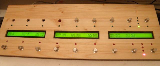
Ich hab jetzt die Midibox12e, soweit fertig, 1Core modul 1 DINx4 Modul 2 Midibuchsen 1 Netzbuchse 12 Encoder 1x 1HE Frontblende 3x Taster 1x 2x20 LCD hängt nur für Versuchszwecke dran, Die 12 Encoder verweisen auf 6 Groups 1 Taster steht für Meta event: "Encoder Slow Speed" Mode when Button pressed funzt aber nicht >:( (Sollte die Encoder die momentan fix auf "fast" stehen per drücken auf diesen Taster kurzweilig auf slow stellen, und somit die Geschwindigkeit der Encoder erhöen-VOTIS ENCODER werden benützt...) 2 Taster stehen für 1.:Decrement Group with overflow & Auto-Snapshot 2.: Increment Group with overflow & Auto-Snapshot (sollte glaub ich die 6 Groups durchschalten- funzt aber nichte >:( ) Also: Was bedeutet "Button NR" und was ist "Button ID", was steht für die Physikalische Pinbelegung am DINX4 Welchen MODE soll ich für diese Funktionen aktivieren? - "ON/OFF", "ON/ONLY", "TOGGLE" Und gibt es eine Möglichkeit, am DOUT MODUL über 8 LEDS die gewählte GROUP anzuzeigen (Led 1= Group1.....? (wenn ichs schaff meld ich mich eh, aber ihrgendwie ist das wie ein Zahlenschloss zu kanacken, nur das es kein "einfaches" 3 Zahlen schloss ist sondern ein (Button nr+ Button id + on/off + on/only + toggle=5 variablen :o ) Hilfe, erwünscht, servus phat edit: Zum editieren der sysex nehm ich: vmidibox64e, release: Sep 25 2004