tatapoum
-
Posts
167 -
Joined
-
Last visited
Never
Content Type
Profiles
Forums
Blogs
Gallery
Everything posted by tatapoum
-
Hi Dave, Have you checked photos from Tohrsten here and Martins here. You can analyse also the space between elements by editing the FrontPanel Designer file. But this space depend of the type of button you choose and how you intend to mount them. In Thosten's design there is a space of 20,32 mm between eah encoder (that's why I think, but FPD tell me there is a space of 19.69, which is not a multiple of 2.54 ?). That means there one empty row on vector board between each encoder. For my design, there is a space of 17,78 mm in accordance with the button size. Even if this sepup seems more close to the LCD display, it lets not a large place for the encoder knobs. With 15 mm knobs, there's only 2,78 mm between each of them. That's why I have to found 13 mm knobs (I'm waiting for the anwser of Albs). I'm only in design phase of my MBSeq, but I hope this helps, ludo
-
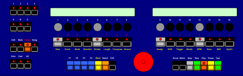
Hi, I totaly agree with you. I'm waiting for my order of the button, the lcd and the 3U rack (I've found one with a deep of 150 mm). That's exaclty the kind of advise I expected for. Because without have played with it, it's difficult to have this approach. And I realize that I forgot the Power button. Take a look the the new design. That's not related to SID, it's the sequencer. The drawing was made with Visio. I use this software at work and it's a piece of art. I can understand why Microsoft has bought it and will include it in Office Pro 2005. Very nice for simple engineering, flowchart, diagramm, etc... But that's not a freeware. Yes, but, I'm waiting for all the elements to see if was I intend to do is possible. I want to minimize the number of screw holes in the front panel and that the button don't go into the case when pushing on it. Something like that this : Thank you all, ludo
-
J'ai donc commencé l'étude. Aller dans ce topic pour voir la façade avant.
-
Hi, What do you think of this front panel design ? Do you think it will be ergonomic, button setup... I will order it to shaeffer, but it's just the first study. The button are digitast. Thank you for your opinion. ludo

-
Salut, Je commence sérieusement à étudier ce sympatique séquenceur. Mon gros problème reste la mise en boite. Je trouve la façade faite chez Schaeffer pas mal, mais relativement cher. Je n'ai pas non plus fait de devis ailleurs. Du coup je ne sais pas dans quel boitier mettre tout ça. J'aimerai quelque chose d'assez robuste et qui ne soit pas forcement rackable. J'ai regardé ce que proposent Radiospares, GoTronic et Farnell, mais je n'ai pas trouvé mon bonheur. Etant donné que le boitier doit faire au moins 37 cm à l'intérieur. Je me demande donc comment vous avez procédez, si vous aviez des bonnes adresses pour les boîters. Pour le moment ce que j'ai trouvé de mieux c'est un rack 19" en 3U de 12 cm de profondeur. L'objet est à 69 euros chez Saint Quentin Radio. Merci pour votre aide et vos expériences, ludo
-
ah mince, ces boutons ont un repère. donc finalement je ne suis pas interessé. merci tout de même. ludo
-
salut, je serais interessé car je pense réaliser le séquenceur. tu as une photo ? le prix de ces boutons ? merci, ludo
-
MIDIbox of the Week (MIDIbox SID of David and Ludo)
tatapoum replied to TK.'s topic in MIDIbox of the Week
Thank you Jurbo, The box is a premade one, except that the holes were made by myself. It's a the type of box made for lab's power supply or measuring device. I buy it at GoTronic, an excellent online french shop for component. It's here, under reference LC740 (150mm x 132 x 80). I've changed the aluminium front for a better looking one because the original contain too much scratches. I planned to put a grounded piece of metal between the transformer and the boards to prevent buzz, but I had to admit that you can not hear it. I hate walwart because I have too much of them. ludo -
Thank you, I've also connected in this way and it works ! Some photos here : http://www.tatapoum.net/photos/sid/ ludo
-
Resencement des Midibox, SID et autres projets ...
tatapoum replied to gillesdeshays's topic in Français
Comme promis, voici la Midibox SID que j'ai faite et j'ai mis des photos ici . Donc l'ensemble est composé : - Core, - SID, - LTC, - DINx4, - 4 banksticks, - afficheur LCD 4x20 - un encodeur avec poussoir, - 5 poussoirs, - 2 diodes midi in/out, - 4 prises midi (in, out, out 2, thru), - un transfo, - un prise avec filtre schaffer, - un coffret elbomec 150 x 132 x 80. Toutes les cartes ont été commandées chez SmashTV, les composants chez GoTronic sauf les poussoirs chez Radiospares, et quelles pièces glanées dans mon bazar. Voilà , reste plus qu'à jouer avec. ludo -
I've ordered an encoder at SmashTV shop, but the pin assigment is not clear to me. In the spec there are three pin A, C, B. Is the C the common one to link to Vs on DIN board ? Thanks, ludo
-
Oui, j'ai bien 9V et 18V alternatif. Mais ça fonctionne très bien, même une fois dans le boitier et après avoir l'avoir laissé foncitonner trois heures. La température reste stable et la tension de sortie correcte. Le radiateur que j'ai mis assez petit quand même. Voilà , j'ai presque fini ma MB SID. Je vous aurais bien posté un petit aperçu de la façade, mais je n'arrive pas à joindre une image... ludo
-
Hum, I tried to attach a picture to a post but I got this error : An Error Has Occurred! The attachments upload directory is not writable. Your attachment or avatar cannot be saved. Except that, the forum works great. I found a tip, there's a RSS feed for this forum : http://69.56.171.55/~midibox/forum/index.php?type=rss;action=.xml ludo
-
Je continue à alimenter le thread... seul. J'ai finalement trouvé un transformateur 220V/18V/9V dans mon rebus. Les tensions de sortie sont un peu élevées et le régulateur du core chauffe un peu. Cependant j'ai fixé un radiateur sur le 7805 et tout fonctionne parfaitement sans trop d'échauffement. Pour ceux que ça interesse, je publierai quelques photo de ma Midibox SID qui sort du son depuis dimanche. ludo
-
Finally I've found in the old electronic parts I've collected a transformer that delivers 18Vac (for SID module) and 10Vac (for Core module). The system works but as I flash the PIC late yesterday night, I didn't take the time to let the unit work for a long time. So I didn't see if the regulator became very hot. This transformer may take place in the box. ludo
-
J'ai posé la même question sur le forum anglais, et Thorsten à répondu : "si tu ne veux pas utiliser l'alimentation d'un C64, il est préférable d'utiliser des alimentations différentes. Une pour le module SID (15V/100mA devraient suffir), une autre pour les modules numériques (7V/500mA sont certainement suffisants). Cela fonctionne avec une alimention simple (j'ai utilisé cette solution au début), mais le 7805 du 'core' devient très chaud, surtout quand il y a des éléments consommateurs (particulièrement les afficheurs LCD avec rétro-éclairage)." En espérant que cela vous aide dans la construction d'une Midibox SID. Pour ma part, j'attends les PCBs avec les composants... ludo
-
Hi Thorsten, I'm please to have a clear answer ! I suppose that you're a busy guy, but if you could write a note about this point in the Midibox SID pages. I'm a little bit sad because I found in the chaos of my archives a nive wallwart 15v dc. I'll study how to power my midibox at the best. Thank you for your help, Ludo
-
Hi ! I've already post in french, but I didn't receive any answer... I'm building a MidiBox Sid with a DINX, a LTC module and a LCD. But something doesn't let me sleep... How to correctly power my future synth ? Thorsten's site is not clear about this point... I don't think to use a c64 psu... So, may I use a standalone 15 Vac power supply, or may I have to use a dual voltage transformer ? I'm affraid that the unit may be noisy if I put the transformer inside the box... Thank you for your experience feedback... If these points were already explain, I apologize... but I searched in vain.
-
Comment alimenter correctement une MidiBox SID ? Le commentaire de Thorsten n'est pas très clair sur le schéma. Il semble que l'on puisse alimenter le Core et la carte SID avec du 15 V. Cependant, le CORE régule en 5 V. Est-ce que dans le cas d'une alimentation en 15 V le régulateur ne chauffe pas trop ? Donc puis-je alimenter en 15 V les deux cartes, ou vaut-il mieux faire deux alimentations séparées (plus complexe) ? La config que je prépare : SID, Core, DIN, LCD et LTC. Merci !