

Altitude
-
Posts
1,184 -
Joined
-
Last visited
-
Days Won
30
Content Type
Profiles
Forums
Blogs
Gallery
Posts posted by Altitude
-
-
^
Cool. Looks like the same design with some updates. The 808 is an outstanding piece of kit, all my braid and solder suckers are gathering dust because of that thing
-
smash never had an Aout available, that was a DIY board only
-
Just talked to him, new batch will be available shortly (1-2 weeks)
-
 1
1
-
-
Ok,
I'll do up a package shortly. FYI, the way it's laid out now is the primary is in parallel for 115V, it will need to be changed to series for 220
-
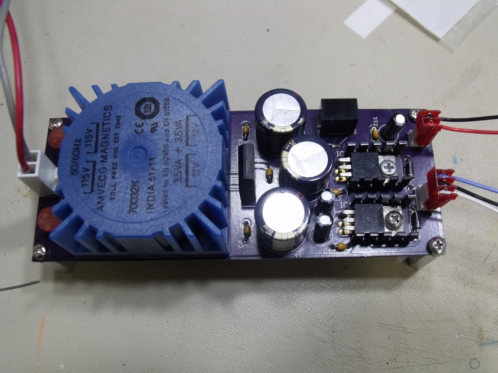
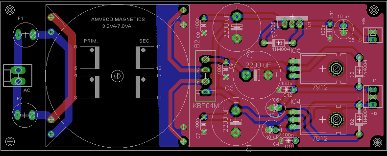
This is based on a previous design I had used in the past with some improvements (smaller size, switching 5V reg). Its a 7VA trafo which gives 580 mA max, not a lot but enough for my needs (size was the big factor here). Standard 7812 and 7912 linear vRegs with a switching Recom R-785.0-0.5 for the +5. Total cost was ~$50 including the board. If anyone is interested, I'll post the BOM and eagle files
-
1
-
-
i've seen a bunch of the originals with the chips soldered in the usa
-
I'd recommend against that stuff, it breaks pretty easily and once you break one lead, you have to replace the whole cable which is major PITA. I use standard ribbon cable with DIL connectors along with IDC headers which allows you to disconnect everything if you need to (you only use half of the connector). It's strong and you never have to solder the ribbon to the board. Alternatively, you can just bite the bullet and use one wire per connection, its a lot of work but much more practical since if something breaks, its an easy fix
-
I actually found that via a post about the JREF (James Randi Educational Foundation) James Randi is a magician who's committed to debunking all sorts of BS about all sorts of things (telepathy, ghosts, magic etc) and has a whole category devoted to "audiophile" equipment. He offers a 1 million dollar prize to anyone who can prove that their cables actually "sound" better than others (via a double blind test), no takers to date.
I remember a link going around for a $500 wooden volume knob that was supposed to absorb "micro vibrations in the pot shaft". These people are the all members of the royal council of morons.
-
-
and the results:
-
-
-
If you have a spare, drop me a line. Smash is busy and I dont want to hump his leg about it
-
They are stereo pairs and effectively 4 separate synths in one box. The noise wont bleed per say but the stuck notes will stay on until another note is played so that you will hear. Personally (having had both) I wouldn't even bother with 6581s. Timbre wise, the 8580s/6582s are identical except there is no envelope bug and the filter works
-
I was planning on using a Meanwell, same thing as my euro setup. This will be in a SEQV4 enclosure so the +/-12 will only be used for this
-
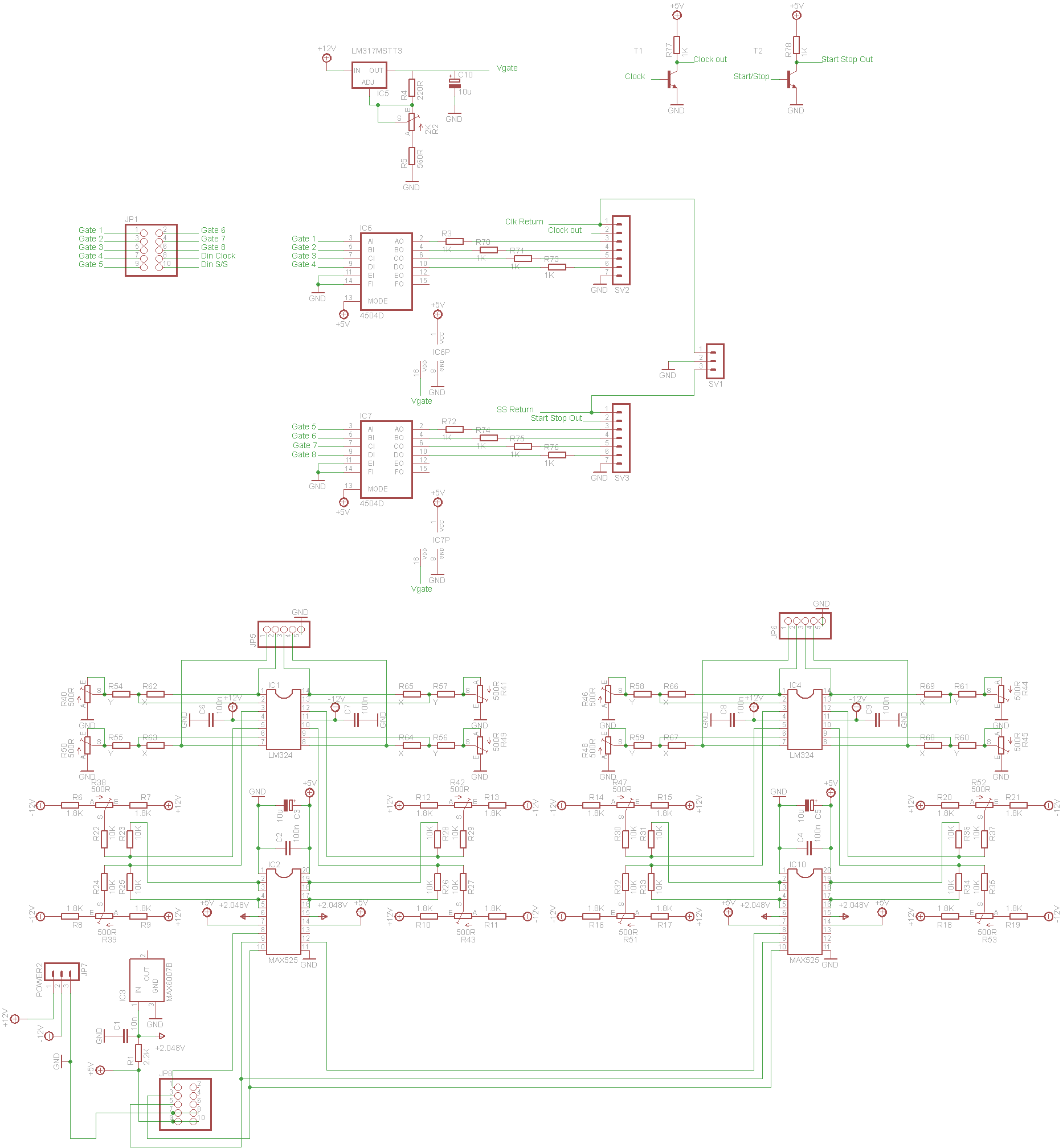
I went with the 525 simply because I had the SMD parts on hand and it's supposedly a better part.
JP8 is the 1:1 pin connection from the core (or it should be anyway, I'll make sure to double check that). I used the NorthernLightXs schematic from the Aout redesign page and that was one of his changes to the original design
The adjustable gate is very handy, I just built a TTSH and without that, I would have needed to build another device to deal with the high level gate requirements for that thing. Figured it would be a more useful add on than the normal 5V level shifter
What do you mean regulated voltage for offset correction? Is there something more needed than the 6007 in the original design?
-
Yeah,
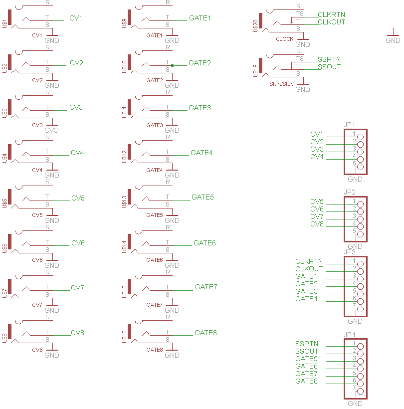
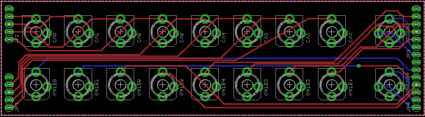
I've been thinking about that, the headers will provide quite a bit of friction so I would only need one or two to keep it together. The breakout board is designed to be panel mounted by the jacks so there is no need there. I went with the cool LJE0352-4R / Kobiconn TRS 8mm jacks

-
5.5"x1.5" I didnt really plan it for a rack. It was sized for my hammond case but 4u should be fine
-
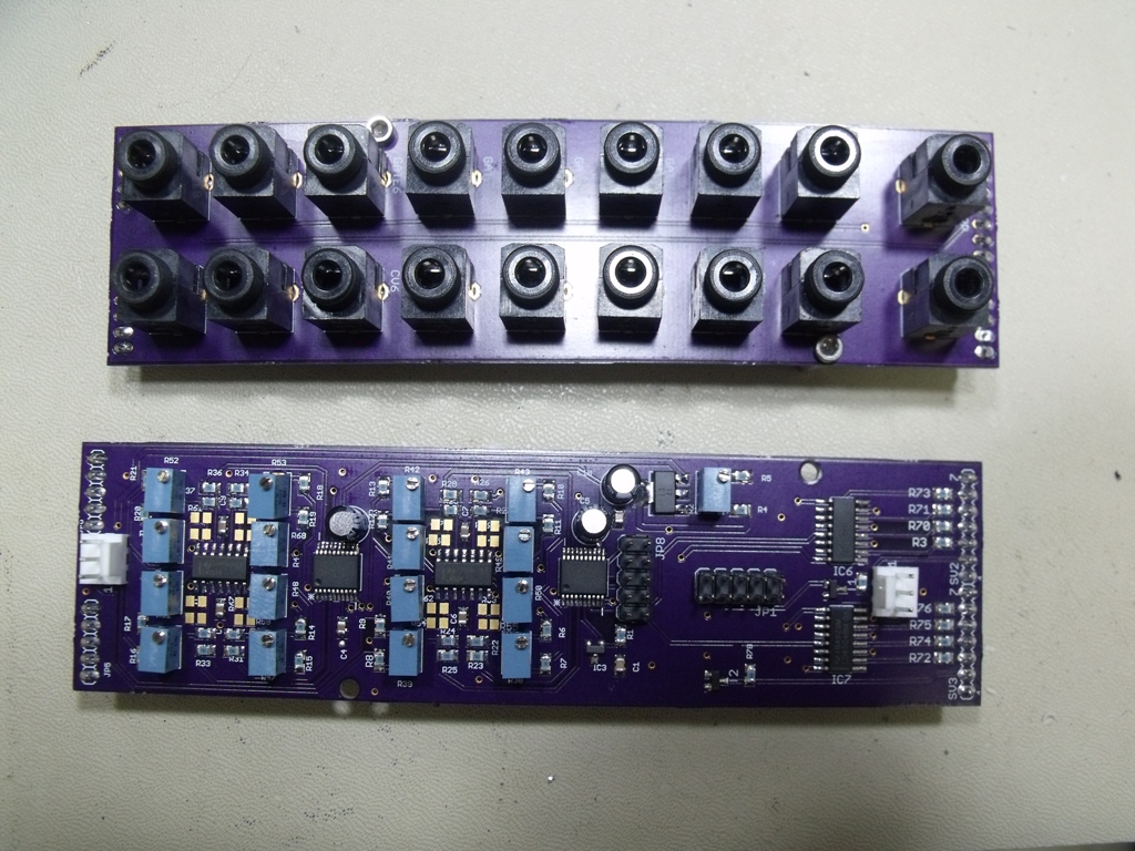
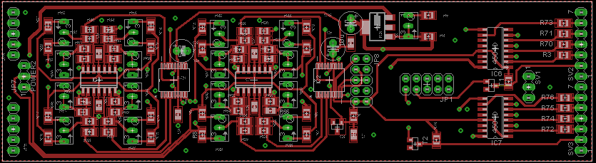
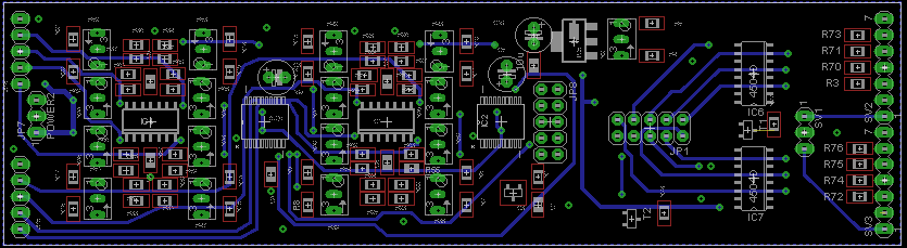
So I have been working the last month or so on a new surface mount based Max525 Auot module with integrated daughter board and level shifter. The level shifter if based on the Midisizer Alf analog board and is adjustable from 5 to ~11V gates. Sync24 is also included via normaled jacks so the signals are run to the DIN port on the 4xIIC module unless something is plugged into the 3.5mm on the break out board.
Critiques/comments welcomed and appreciated
-
1
-
-
Skunks:
I heard no difference between the TI and Recom parts. The old TI part is long obsolete and it was twice the cost. I've been using the Recom parts for everything and I highly recommend them. No issues at all
-
I'll call them and see what they can do, it's an obsolete part (hence the price) but a VFD for $18 is a VFD for $18... I've never seen the regular part, how does this differ? The only difference I could spot was the little bulb on the front of the display..
I ordered a set of the colored covers so I'll snap some pics once I am up and running..
-
..
Switching PSUs with high switching frequency are regulated, so we have to bypass regulator. But they have a switching noise/crackle. Is it a good idea to grab a switching PSU on e.g. 15v and pass it though a 7812 ? Will this remove the noise?
...
This is how I do it. I use a Triad 15V 1.5A switching wall wart which feeds a 7812, a R78C9-1.0, and a R78B5.0-1.5 (for the 9V and 5V respectively, those are switching Recom Vregs). This set up allows me to power the whole thing from a single DC supply (a very small one at that). I retrofitted my box coming from the big C64 brick and was careful to check for any noise level changes and there were none. Same thing for the 15V DC brick, initially I used a linear one but it was almost the size of the C64 one and again, no noise going to the switcher
-
So mounting holes match up?
-
you're going to need to buffer that serial line if you plan on running a cable anything longer than a few inches
MB-6582 DIY C64 Power Supply replacement
in MIDIbox SID
Posted
Not sure why you keep insisting on having a 9VAC rail, there is nothing you need to power with an AC source, it's rectified to DC anyway and was only built into the design since the C64 PSU only has 9VAC and 5VDC power and those needed to be combined to get the 14+VDC needed for the 12VDC vRegs. You can use a 12VDC switching wall wart and not have to deal with transformers or mains voltages at all. A fully stuffed MB6582 draws just over an amp using a 12VDC adapter, going to some crazy 5A switching device with 3 outputs is a waste of time and money. I use the Triad 1.5A switching wall warts they have at mouser and one of those plus a swtiching 5V reg for the digital side will run you all of $25
Besides, 9VAC isn't enough to power the device anyway on its own since there is a 1.4V voltage drop across the bridge rectifier and you need a 2V overhead for a 7809