Rio
-
Posts
727 -
Joined
-
Last visited
-
Days Won
9
Content Type
Profiles
Forums
Blogs
Gallery
Everything posted by Rio
-
hi george, inside this document, you will find detailed information of the LPC17 connectors: http://www.ucapps.de/mbhp/mbhp_core_lpc17_pcb_v1_0.zip Have fun building your seqv4 ;) greets, rio.
-
Necessary PDF documents from the LPC17 based core page: http://www.ucapps.de/mbhp/mbhp_core_lpc17.pdf from the MIDIbox SEQ V4 -->User Manual -->Hardware Options Page: http://www.ucapps.de/midibox_seq/mbseq_v4_din.pdf http://www.ucapps.de/midibox_seq/mbseq_v4_dout.pdf http://www.ucapps.de/mbhp/mbhp_core_lpc17_midi3_midi4_extension.pdf from the SD Card Page: http://www.ucapps.de/mbhp/mbhp_sdcard.pdf Greetings, rio.
-
Hi George, please Take a Look at the MBSEQV4 Site --> Tutorials --> Hardware Options. Everything is well documented, also PDF documents for interconnection to Sdcard, iic, DINX and DOUTX. Greetings, Rio.
-
wow. fine ;) thanks again.
-
Could it be a Bootloader message? Greets,
-
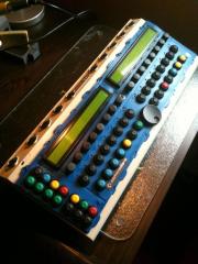
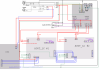
 Backside Midibox SEQ V4 - Upgrade from V3 with additional Midi IN/OUT 3 + 4 and 4x IIC and 4x LTC 8x IIC (hacked)
 -
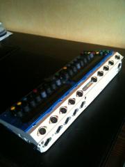
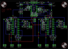
 Frontside Midibox SEQ V4 - Upgrade from V3 with additional Midi IN/OUT 3 + 4 and 4x IIC and 4x LTC 8x IIC (hacked)
 -
Hi Community, a) I see that the additional CCs of "Mixer Map" are assignable in a range of 0 to 112. Is there a reason for that purpose (not max 127 (0x7F))? b) if the sequencer is running then multiple dump-calls of mixermaps will hang up the application (and sometimes the send routine will cause a delay for sending that mixermap in contrast to MBSEQV3). c) I miss the cc 111 implementation to dump a special mixer map, like it was implemented in SEQV3 (I would be glad if that could be adapted :smile: ): CC#111 (0x6f) Dumps the values of a Mixer map (0..127) little request in that mixermap section: I don't know, if you like the feature, that the user can decide whether any of these additional CCs (1-4) could send before all the standard Mixer CCs (like Prog.Change) will send out, so that e.g. Bank.Change Commandos (CC 0 and/or CC 32) can be supported by that mixermap (so that it will send out ahead of Prog.Change). c) the manual of V4 at point "Pattern Screen" says: GP buttons: the 128 patterns are enumerated from A1 to h8. The 8 buttons at the left side switch between A-H/a-h (press the button twice to select a "lower case" character), the 8 buttons at the right side are used to select the pattern number (1-8). ..but I can only choose between A..H and not lowercase Patterns. Is it a bug or are there now only patterns from A to H possible for a bank? d) incomming MIDI CC will be only recognized if Ext.Ctrl -> IN is not set to "ALL" hey tk, don't take all my suggestions/reports as negative points - that new application is a superb application and i am impressed again! So big thanks! and a lot of success & fun on doing this. Greets, rio
-
Hi TK, a big thanks to you from me! for the new Midibox SEQ V4 upgrade, which I had finished last days! The application looks great and a lot of points look very similar to SEQV3, which makes my life easier ;) Go ahead! I like also the little gimicks like loader screen etc. big thx and Greets, rio
-
Hi all, i have build up the BPM LED digits exactly like: http://www.ucapps.de/midibox_seq/mbseq_v4_bpm_digits.pdf but i'm not sure how to setup it correct, because all LEDs of every segment are "on", when I start and run a sequence. I use these 7 segment digits: http://www.dl9usa.de/Ebay/009/vqb37.gif and these MBSEQ_HW.V4 settings (which must be wrong :D): ################################################## # Optional BPM digits ################################################## # set to 1 or 2 to enable the 3 optional BPM digits # 0: BPM digits disabled # 1: BPM digits with common cathode # 2: BPM digits with common anode BPM_DIGITS_ENABLED 1 # define the DOUT shift register to which the segments are connected (0=disabled) BPM_DIGITS_SEGMENTS_SR 5 # define the DOUT SR and pin to which the common pins are connected # we are counting from right to left # Example: 140.5 BPM: (COMMON1 = .5, COMMON2=0., COMMON3=4, COMMON4=1) # SR Pin BPM_DIGITS_COMMON1_PIN 4 3 BPM_DIGITS_COMMON2_PIN 4 2 BPM_DIGITS_COMMON3_PIN 4 1 BPM_DIGITS_COMMON4_PIN 4 0
-
if I connect SD Card - LF33 will be very hot in a short time
Rio replied to Rio's topic in MIDIbox SEQ
thx correct, i have found a short cut on sd card mount. so Vs was connected to Vcc. greets, rio -
Hello, is it normal that LF33 will be very hot in a short time when I connect a SD Card to J16? There is only the bootloader installed and after inserting SD Card -> the LCD shines a bit weaker and Core's LED switched of and it restarts after removing SD Card again. With Card inserted the core won't complete boot. The core gets power via external 5V. Thanks for help. Greets, rio
-
hey thx, LED_MIDI_OUT_COMBINED / LED_MIDI_IN_COMBINED is a common - "not port-depended" - indicator. correct? Greets ,rio
-
Hello, i need help - where should I connect Tx and Rx LEDs for MIDI IN 1 2 3 4 and MIDI Out 1 2 3 4 (similar to IIC Tx/Rx)? Which port/connector can i use? PS: I found something about MIDI 3 OUT/IN in this document http://www.ucapps.de/mbhp/mbhp_core_lpc17_output_buffers.pdf but I don't kn whether its for LEDs Output. Thx for any help. Greets, rio
-
ah ok, now i got it ;) Thanks.
-
So I don't understand what I have to connect, when I want to use USB power. Does it need to connect to PSU-Circuit [J2 --> 3,3] too (as J2 INput?) or is it not necessary? And if yes, how I have to connect it correct, if I want to use my C64 PSU as a secondary supply. Your decription for the connection confused me, because I don't know, which way the 5V-USB Power have to go :D Greets, rio
-
hey thx for all your informations.
-
hey, you mean, i don't need extra LTC modules for that case? I have 4 IIC Modules. In my current box (V3), I have used 4 IIC + 2 addional LTC Modules to duplicate IIC Port 3 + 4. Now I have also 2 more LTC boards, but it looks it could be very close inside my case ;) - so yes i am interessted how to optimize my box maybe with left out LTCs, but with 4 duplicated MIDI-OUT Ports. greets, rio
-
Hello, this link/schematic http://www.ucapps.de/mbhp/mbhp_core_lpc17_output_buffers.pdf contains: So it is possible to connect multiple MIDI-OUT instead of using a lot of LTC-Modules anymore (for space-saving inside the case)? Or does it mean that LED output can be multiple only? Greets, rio
-
So it fits for my needs? Greets,rio
-
Hello, i want to use the 5V DC pinout of my C64 PSU to supply the SEQV4. So i want connect the 5V directly to J2 (with C8 mounted to J2 (all in front to J1 left out)). Could be the LF33 in this circuit too hot (?), because the CPU delivers max 1A - or should it work fine? Greets, rio
-
Hi, I want to upgrade my MBSEQ in near future. How can I copy my seqv3 data into seqV4? Greets, greets.
-
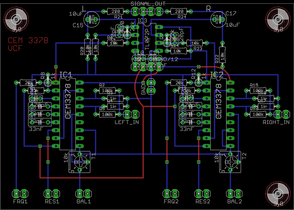
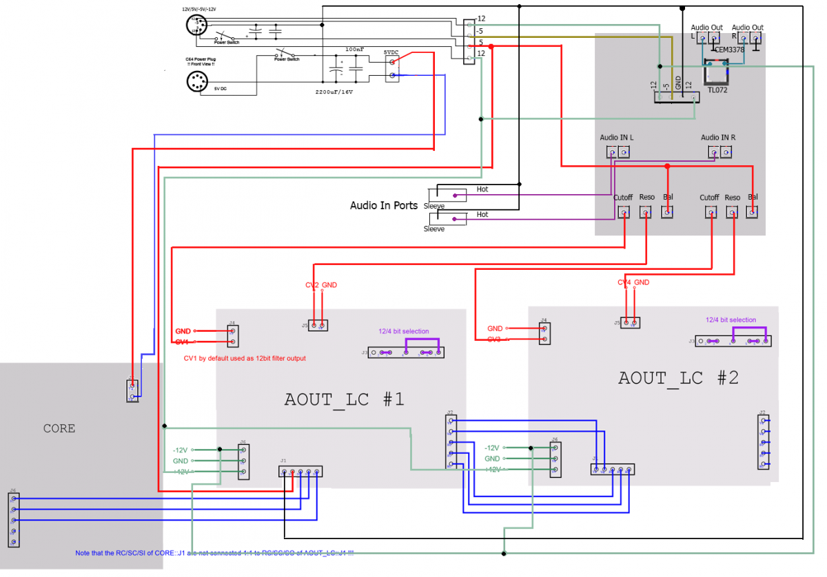
Ok, how i had said, i upload a new PCB and a Schematic in attachment. Maybe you have some improvements to that. The signal-to-noise ratio is not so high in contrast to my other audio devices, so if you have some better ideas about that, let me know. CEM3378_handmade3.zip
-
i will upload a newer CEM PCB and a bit more infos for better result soon.
-
Hi, i know, thats an old thread but I searching infos. Correct me when I am wrong: Demym wrote: http://www.ucapps.de/mios/j5_dout.pdf --> shows 220 Ohm ! (so demym, your info of 470 is wrong...) Greets, rio