TheAncientOne
-
Posts
726 -
Joined
-
Last visited
-
Days Won
2
Content Type
Profiles
Forums
Blogs
Gallery
Everything posted by TheAncientOne
-
I tried to get onto the Renoise Website and both it and it's mirrors seem to be 'off air'. The new version only came out on December the 12th, so I hope they haven't been swamped. If anyone else can get on, I'll assume it's my ISP and try from another location. Oh, and Happy New Year everyone.
-
If you are doing the LED probe trick ALWAYS put a resistor in series with the LED to limit the current. If you use a very bright red LED,then 1K is good. Otherwise you always risk drawing too much current from the pin of the chip. Whilst on the subject, it's worth remembering that when driving LED's from a chip, that there is a maximum current that can be drawn or pulled from the package, (the common terminal being the VCC or ground pin). For example 74HC595 used in a DOUT: you can draw 20mA per pin on the outputs, but the maximum Ground or VCC pin current is only 70mA, so the total draw must be less that this. If driving LED's then 8mA per LED is about the max, unless they can never all be on at once.
-
We've all pulled stunts like this: I once put the live EPROMS for a project in the eraser and the clean ones in the copier..... it cost me a bit more than 5 days. You do a tremendous amount keeping this forum on it's feet. It was a minor error under stress, that's all. I think you are owed massive props for actually migrating the forum to a new format. Best wishes
-
Yeah - I'm kind of slow at these things. Popped up in an email and I thought I'd repost. Most programming jokes I get are too 'in house' to repeat. Sorry, Oscar.
-
http://en.wikipedia.org/wiki/LOLCODE
-
One additional trick, once it's all soldered and done, run a bead of hot glue along the solder end line. This si used in a lot of commercial products, and helps prevent breaks due to flexing. I often do it with LCD's.
-
Pactec PT-10 Order - Reloaded - new price
TheAncientOne replied to TheAncientOne's topic in Bulk Orders
NO - it's looks like a massive price hike. Checking the maker's site doesn't do much to raise the gloom either: http://www.pactecenclosures.com/Plastic-Enclosures/PT-10-pricing.html. In the days of the printed catalogue they at least had to keep the prices for 3 months. When I did a batch before, I bought from the UK distributers Acal, but they are showing no stock, so we would be in for a long wait, even with a better price. I'll check with RS, but I think we might just have to suck this one up or find another case. I'll revise things when I know what I can do. -
It's a strain gauge design, like the sidestick on the original F16, (which was rapidly replaced because it didn't provide any force feedback). Strain gauges are delicate to handle, tricky to implement, and need a bit of fancy analogue stuff to function. buying one from Nord probably doesn't get you the interface, just a spare stick. They finally provide a voltage output. You might be easier served with some kind of softpot arrangement.
-
Beautiful work Wilba, and as in the MB6582, not just outside, but inside. The no-wiring makes this as near to an "off the shelf SID stnth" as can be made, as I see it, and at a fraction of the price of a SIDstation! My congratulations to both you and Nils
-
MB-SEQ V3/V4 Control Surface PCB and matching case
TheAncientOne replied to Wilba's topic in MIDIbox SEQ
It might be worth going more seriously professional and using a sub panel with countersunk through screws, and putting the fancy engraved trim panel on top of it. The good bit here is that it separates the aesthetic and structural panels, so the sub panel can be steel, and does not have to have accurate switch holes, just cut throughs. I used this for a few other synth designs, (and no pix, my proto panels are sub ghetto at the moment). On trick I did was to have a hinged panel on the back for the PCB in the module, so it was compact, but easy to work on when I needed to. -
MB-SEQ V3/V4 Control Surface PCB and matching case
TheAncientOne replied to Wilba's topic in MIDIbox SEQ
This guy on ebay does some useful bits, including a ready to go SD socket for about £7.50. SD card holder He might do a better price for bulk. -
MB-SEQ V3/V4 Control Surface PCB and matching case
TheAncientOne replied to Wilba's topic in MIDIbox SEQ
Rapid don't do a rectangular cap that would fit. The x0xb0x uses the caps Wilba uses, which are 3.3 mm only, and only seem to be available Stateside. I have a maddening problem from that run too - I found out, too late to do a return, that one bag of 100 caps from Mouser only contained 99, so I'm 1 white cap short for my own last x0x. I need to wait until I can do another big order to Mouser. Moral here is always to order a few extra. On the sequencer front, I've also got some High reliability 12mm standard ones from Omron, (they might be actually made by Alps), which are specified for 10 times the number of operations than the usual 12mm tacts. I intend to do my own panel, and perhaps use round buttons. With ergonomics or panels, I often do a scruffy hand drilled 'ghetto' style panel, and use that to work on the layout. I find that, as far as using a device goes, sometimes there is no substitute for actually working with the thing to get the layout right. Those Re-An encoder knobs you got are the best thing I've found for the sequencer front: knobs like the ones on the MB6582, whilst looking great, would mean a very wide, untidy spacing, or a double, staggered, row, to get a good finger spacing for me. A trick I've been trying, to help with layouts, is to stick bits of self adhesive magnet strip to the back of some knobs and button caps, and juggle them on a bit of mild steel sheet, with graph paper stuck to it. I'm just making up some mock displays to go with them. Not quite worked out a way to do toggle switches yet. I'm currently working on layouts for 3 analogue sequencers: a Ray Wilson 16 stepper, a Klee, and a Milton. Along with the MB Seq and a P3, I might own up to a slight sequencer fetish.... (edit for typo) -
MB-SEQ V3/V4 Control Surface PCB and matching case
TheAncientOne replied to Wilba's topic in MIDIbox SEQ
On the topic of 12mm tact switches, I've got 200 of the Rapid 78-0640 going cheap. These have a 3.8mm square actuator, not a 3.3 as on the Mouser ones. ( got caught out by this doing a bulk buy for the x0xb0x). There seems to be two 'industry standard 12mmm switch' types.... Rapid have both round and square caps for them. -
An Idea: There are a vast range of digital potentiometer chips available, (Farnell show 300+ in the volatile type, and 140 or so in the non-volatile type). If an I2C/SPI version were chosen, the aout could be dispensed with, though since most are 256 step, there might be zipper noise issues in doing AM. A small board of 8 duals would fit nicely in the MB 6582, as well. there are also SMT singles that would fit nicely too I've used the older Maxim/Dallas ones to implement a remote volume control for poweered speakers, which used opto isolated RS485 loop to control the chip via an 8 pin microcontroller, (I can't remember which one it was - I did the spec and initial design, the customers micro wizard did the programming). The pots come in Log models too. I might have a look once I get back to building.
-
Cancelled due to ridiculous price hike. Sorry folks, got way to expensive for now. Will take another look towards Sept 2010. (original post) I've had to rewrite this, because Pactec have put their prices up considerably, and the UK price reflects this. The only other UK supplier is ACAL, and they have no stock, and are drawing direct from Pactec, so we wouldn't see much improvment. Last time I got them from ACAL, and delivery was very long. Do another 15 people in UK or Europe want a PT-10`case (for the MB6582 or the x0xb0x)? If enough people want one to warrant an RS order, I don't mind doing another batch. Since these would be coming through my UK based, VAT registered, Limited Company, I have to show a small (5%) mark up. Anyone in a non-EEC country would get it VAT - free. If 15 people want one, the cost would be £25.24 plus Packing, Postage and Paypal fees. This is a ludicrous price hike in my opinion, but there is not much in the way of options. Mouser have them, but they work out at 26.60 plus an unknown amount for import duty, plus PPP; even worse. I've emailed Pactec themselves, to see what the cost of a standard carton, (16 - 20 as I recall), would be, shipped direct, because the baseline price here is about $27, though I need to see if once the carriage, customs and handling charges are added, it's enough to make a diffference. Stay tuned, and I'll see what I can do. One thing: If I go for an import, we will need to move fast once I get the price.
-
Great for a rack mounted mixer. Or a filter bank, or one of the expanded versions of Ray Wilson's Soundlab. http://www.musicfromouterspace.com/.
-
Yes it is: can be 'slang spelled' as 'ElCo', or 'Elko' or sometimes 'ElCap'. I tend to use the longer name of 'electrolytic', usually. I think ElKo is the German short name - they spell 'Kondensator', but German technical names always sound the most impressive anyway.
-
You've either put the elco the wrong way around (reverse polarised it), or you may have a rectifier problem that is putting AC on the cap. Either way, you must replace it - it won't be safe after that swelling. Best bet is to take the chips out, replace the cap, check the rectifier position, and check to make sure there isn't a shorted diode in the rectifier, or a solder bridge, then power up and test for the right regulated voltage with no chips before re-installing. If it's the right way around, and the rectifier is working fine, the you may just have had a bad capacitor.
-
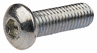
IMHO, 'button' head screws look better than Countersunk, in that they don't require a precise countersink fitting, and there is less risk of a ring of exposed bright metal around the screw. Here are some examples. If 12mm long would do, then I could get a box of either black or stainless from RS and post them around. I reckon the stainless might look good, myself. If people want to be really fancy, I can get them in Torxtm too.
-
No, but if it was by the same team that later did Watcom 'C', it must have been pretty good. It seems to have been done for a few machines from the Vic 20 to the IBM 370, which is quite a range! I don't think it was available outside Canada though - I never saw it in the UK. The original Commodore BASIC was like most of the other BASICs of the time:- pretty horrible, not helped by their operating system which seemed to require 'sys' calls to do anything interesting. C64 was probably the best gaming machine of that generation - all that RAM, and the SID on top of that. THe only game I really played on the BBC was 'Elite', which showed how far the machine could be pushed. BBC BASIC was quite on the leading edge at the time, developed by people who'd learned on things like BCPL, it had really good control structures, built in multi-pass assembler, procedures and functions, multi-dimensional arrays, and was very fast. Pretty good graphics commands too, though that could get complicated. I went to a demo of the then 'New' ARM based Archimedes, versus the 'New' Compaq 20MHz 386: the Archimedes was way faster running BBC BASIC (interpreted), against the same program written in MS Basic on the Compaq. The Compaq rep. said that the 20MHz machine was only a stop gap, and they would soon have a 33MHz machine, which would be faster. The man from Acorn started laughing, then explained that the Archimedes' processor was running at 8MHz. Acorn had a bit of a posthumous last laugh: There have been far more ARM chips made than Pentiums, (the last big number they passed was 10 billion). Soon appearing in a MIDIbox sequencer near you....
-
I was away this weekend, and missed the 'Console Combat' event in Manchester, (local to me, too). One guy was showing a BBC Master with a SID hooked up to the 1MHz bus, so he could get seme real chiptune goodness. I wish this had been around 'back in the day', the BBC's operating system and structured BASIC, (and other language options), made it by far the best programmers machine, but the little Texas soundchip was just sad. There was the Music 500/5000 option but that cost a fortune, (I know, I bought one - still got it for that matter).
-
Cool idea Doug - I can imagine that hooked up to a couple of rows of analogue drum modules. Perhaps some kind of VCAs could be 'wrapped' around the modules for a general purpose accent system. A nice modular, flexible idea.
-
When experimenting, always use the resistor, it is too easy to fry a transistor or IC output stage with a direct 5 Volt connection. It would be possible to drive the system with DOUTs, but there might be timing issues with the latches. Over the weekend I'll have a look at it - driving the board through the normal interface may not be that hard To get the proper range of accents, you will need to master art of driving the latches. Best wishes
-
I'd try a 4K7 resistor, connect one end to +5V and touch the other end to the base of Q1, (the junction of R1, R2 and the base of Q1). I think you should get some sound, even with nothing applied to the accent input.
-
Like I said - you need a board with 1 data port, (8 bit, but only 6 used), and 10 I/O selsct lines, which could be decoded off another 4 lines. 8 data writes to set up the accent latches, then write the required lines in latches 1 and 10 high then low to trigger the sounds. As I said, all you need to test them are some switches resistors and wire. Sadly a standard Arduino has only 13 digital I/O lines available, so you would need (say) 2 74HC138's cascaded to decode 4 lines to the 10 needed, (actually 16, so you could use the other lines to address peripherals). A MIDIbox core would be better, because the MB808 code would be a good start, and it has more spare lines, as well as an LCD interface. Downside is the programming is harder. I have used a tecnique like this to address some other drum voice card, years ago, driving it off the 1MHz bus of a BBC micro, and later converting it to run from the parallel port of a PC. I can't find the data on the last one, it seems to have got lost, though we could get quite good beat patterns from a program written in QuickBASIC on a 486, (which tell you how long ago thta was!). Hope this helps - it would be a well cool project to get running, and since, from a repair point of view, the sequencer and buttons in a 909 are more of a fail point than the voice card, you might have a way to revitalise one or two dead 909's.