TheAncientOne
-
Posts
726 -
Joined
-
Last visited
-
Days Won
2
Content Type
Profiles
Forums
Blogs
Gallery
Everything posted by TheAncientOne
-
It looks as if 6 bit data is presented on CN2, and CN1 selects which, (4174), latch the data is sent to. 8 latches implement simple 6 bit digital to analogue converters, and the other 2 seem to be triggers Some of the latches provide accent volume data, eg IC3 is the bass drum accent level. It would seem that the cycle would be to set the latch contents for the accent levels on the drums you want to use, then issue the triggers through the other latches. I haven't time to take a deeper look at this, but yes: a MIDIbox to 909 seems easily possible. You could use a manual pair of switchboards to test them out. You'll need 6 plus a reset on CN2, then 10 on CN1. Switches should have something like 4K7 pull up to 5 Volts and switch to ground, (switch 'ON' = a zero input). The data may be inverted. Since the resistor networks usually consist of 6 identical values, (unless they are a 'special'), then there may only be 6 levels of accent. IC1 and IC10 are the trigger latches. Hope this helps.
-
I grabbed the source for a look. Obviously built upon some other work: the comments are a mixture of French and English. The difficult bits would probably be in the setting time and date mode, where more of the display is used. It is possible to do, from the way the source is written, but it will be quite a lot of work. A few things I googled up: Max 6959 Project These guys sell ready made I2C LED 7 segment modules Or if you want to get really silly A last thought: perhaps you could add a real time clock module to the 'MIDIbox monitor display system. Use the I2C clock design from the article you posted, then write the I2C read/write stuff and use that instead of the main loop in the monitor Hope some of this helps. Mike
-
My French is not good enough to read the site. Is the source code available? If it is, then you could use some of Philips' I2C to 7 segment driver chips, but you'll need to re-code it. Translating LCD commands to a 7 segment set is a job for another processor at least - better to re-code the main firmware. If the code is good, and structured, then the needed mods will not be that hard. Is it a special type of clock? there are plenty of LED clock designs around, and I think there are some single chip ones still around as well, (though not sure if the do the date as well as the time).
-
Thanks for the MP3 - now installed on her iPod. Her kids (7 and 10), commented 'Cool' and 'It rocks'. With this spectrum of approval, I think you need to think about an album!
-
MB-SEQ V3/V4 Control Surface PCB and matching case
TheAncientOne replied to Wilba's topic in MIDIbox SEQ
An engraving comapny I talked to locally suggested back engraved acrylic. That way the letters can be filled, but the front panel is smooth, and stays clean better. Back engraved acrylic over alloy sounds like the best of both worlds, to me. -
Lovely work TK. And a request from my girlfriend; when I was watching the video last night on her PC, she sat and listened and then asked if she could have an MP3 of it. Then, looking at the sequencer, said "When is yours going to be finished? I want to try that". Could you post an MP3? I haven't a clue how to extract one from Vimeo! Again, great work, both on the design and the music - it must be a ubiquely satisfying experiece to create your own music on tools you created yourself.
-
Another Nice DIY Sequencer, with kits
TheAncientOne replied to TheAncientOne's topic in Miscellaneous
By the way the strange vibraphone music is a rather retro UK joke. Paul Maddox used it in his 'Building Gorf' video, and Chris followed on with it for the case video. It's become a bit of a retro motif in 'something I made' clips. There was a famous UK artist aclled Tony Hart who did programs for children's TV. Starting with 'Vision on' and then later 'Take Hart'. He always had a gallery section, where they would show artwork children had sent in, accompanied by that tune, It's called 'Leftbank 2'. The programs were very advanced for their time. One small feature was an animation called 'Morph' done by a very young Nick Park, who later found fame with 'Wallace and Grommet'. Looking at the website for 'Vision On', I remembered they also had a character called 'The Prof', which is perhaps who my friends were thinking of why they gave me the nickname. Tony Hart was an inspirational genius - he died earlier this year at 83. I think a lot of kids got into art because of him. We're talking very retro: 'Vision On' ran from 1964 to 1976. -
Paul Maddox has done kits/PCBs for his new baby sized 8 step MIDI sequencer 'Gorf'. Paul has done some amazing synth designs including 'Monowave' a mono PPG type system, and PolyDAC - a multi channel MIDI->CV. You can see them on his site. Details here: Gorf Build blog and PCB info Gorf Blog I've got the board, just waiting for the pots to arrive before testing. The plastic case, (see blog) looks good, but I think mine is going in an actual box. Hope it's of interest. I have one set of switches spare if ayone wants to build one.
-
I'm with you guys on the opto-isolator idea. I plan to connect to an analogue synth: these things have +/- 15 Volt supplies and a bit of bad or careless patching can trash logic chips easily. If you just blow a shift register- no problem, but if the output stage in the chip went short to 5 Volts, then ther is a more serious possibility of other chips getting damaged. Another thought is that with optos the fairly noisy ground of the MIDIbox gear will not be connected to the analogue system, helping keep your background noise lower. I have had a small experiment with some high speed optos, as a way of isolating the MIDIbox data paths, and it seems to work. There are quite a few good design for I2C isolators too, which might open up the possibilities of an isolated and possibly remote CV output stage. I've had no time recently, but I will get back to this as soon as I can get on with my electro-music stuff.
-
Superb case - and a very cool overall design.
-
Experimental controllers sensors ribbons et cetera
TheAncientOne replied to clem!'s topic in Design Concepts
This company in the UK sell a large range of resistance wires, though they are not that cheap. I've bought from them in the past to make foam cutters. http://www.wires.co.uk/acatalog/nc_bare.html They are a subsidiary of this company http://www.scientificwire.com/ -
Evil usernames anyone?
-
I have been drawing you designs for a 32 pin backplane that uses DIN 41612 connectors, (with any arrangement of pins, because they are all in parallel), to carry power, I2C, CAN, Audio etc for a rackmount verion of a 6 SID MIDIbox, using a eurocard sized perfboard for a core and 2 SIDs. By running the other I/O along the 'plane', I will then be able to plug in CV and filter boards. This will certainly come into the 'messy' area. The advantage of borrowing old style computer and industrial control style here is that I can start with one board and add on. The reason for 6 SID's is that I want to have a remote control surface using CAN, and that wiill 'eat' the other core, but not have any SID's. Using the proper CAN interface chips at each end of the remote cable should ensure reliability, and I will probably run 24 or 48 volt power to a little switchmode module in the remote to keep the power current in the cable down, as is done with Power Over Ethernet (POE), devices. Looking at the original BMOW, one thing to remember is that many Supercomputers and 'Big Iron' mainframes used wire-wrap for all their backplane connections and custom boards, and they were very reliable. It was regarded as just as reliable as solder, and in certain cases, more so. People who talk about proper wire-wrap corroding are usually mixing it up with one of the IDC prototyping wire-wrap systems, real wire-wrap connections form small cold welds at each pin corner of the wrap. that's metal to metal, 20 + times. It does look messy, but it's clean and relatively easy to do. I only wish I could find some of the 'kapton' insulated wire that went with the Cut, Strip and wrap bit I have for my powered wrap gun. I could work much faster that way.
-
I can sell you 6 CEM3372's if they are of interest - similar type of part - though i doin't know what the real differences are.
-
Thanks - you have in fact found a later, better, updated copy, Perhaps it should have an SVN..... Yes, that's one of mum's hand made originals, Her own design and stitchery. She's basically a textile artist, though at coming up on 80 she's slowing the pace down a bit. She still doesn't wear glasses. I got her a small kit from Leah Buechley' site, but she hasn't done it yet. http://www.cs.colorado.edu/~buechley/diy/diy_tank.html Coming back towards topic a bit, A thought, you could make the first wearable MIDIbox appliance. Thnking along random arty lines, I seem to remember that you have done some graffitti artwork, have you do any 'throwies' yet? Leah did a wall mural with conuctive paint and LED's it's on her Flickr pages here, now a MIDI driven music interactive wall mural - that might look kinda cool. A made a bunch of Throwies for some friend's kids. I used high intensity LED's, a flasher designed to max out the battery life, and ex hard disc magnets. For months I could see one flashing gamely away from a railway bridge in Machester, edited for typos
-
Ontopic.... I once made a list of the ones I'd actually done something useful in. It was scary. More scary was how many I can't even remember any more. I used to write in APL, but now I can't even remember what those funny squiggles mean. Chill anyone? I can still understand the EMS language, and I came to that by accident trying to decode an old performance written in it - it survives as Mouse . The link also throws up some interesting EMS stuff. Other ones I've used once or twice include Fortran, COMAL, BCPL, FORTH, microProlog, CORAL 66, (OK I amit once - and never again). Still keep meaning to learn LISP. Have you ever seen that file about shooting yourself in the foot in different programmiing languages? My favourite was: (Warning to most MIDIboxers: this joke may be too old school for anyone other than us ancient geeks) OK, but you better see what you're up against: and this is a bad picture of one of her minor pieces....
-
Interesting to see that he managed to get a MultibusTM wire wrap protocard. They cost a fortune back in the day. I wired a couple as big as this, one of which was for IRCAM. It was a DEC LSI 11 format card, with some, (at the time) awesome High speed signal processor, including some TRW hardware multiplier chips that cost about as much as a whole, (cheap), PC does now. About as powerful as a DsPIC. I think I got into the same groove my mum does when she does embroidery, (She did City and Guilds needlecraft when she retired from teaching - her embroidery work is seriously good). You just sit there with your wire wrap tool and your netlist and get on with it. I used to do a set number of wire per night, the next night I'd test the previous nights run, by beeping it through with a continuity tester, then do another batch. I only ever had one not run first time, and that was because the designer had done a patch and not told me. If you are methodical, it's not hard, though it's a bit scary the first time you power the thing up.... It's cool to see a board like this now, for me, because it shows one of my favourite digital prototyping tools is not dead yet! I guess the flip side if this approach is making the whole thing on one big chip using FPGA. There are some cool ideas for this type of thing on ZXGate I've just noticed they've done Jupiter Ace on one chip - I'm up for that, I was going to build a replica anyway, as that was the first processor I ever hitched to a synth, as a test for controlling a synth with an Apple ][ using FORTH. I couldn't keep th Ace and always fancied one. If you want a fast interpreted language, with a small software 'footprint', then forth is an interesting way to go. People like TK can usually do as well with a good macro assembler, but FORTH is quick to prototype in. The AMPLE language that controls the BBC Music 500 was a FORTH derivative. Most Music done in it was a bit cheesy, but a hint of it's power can be heard here: Music 500 Syncron Sound. More details are here: http://www.colinfraser.com/m5000/m5000.htm. The whole site is worth a look - this is the guy who designed P3 and a host of other goodies. Meandered enough for now. Thanks for posting this link - anyone who builds a FORTH computer get extra points from me!
-
@Stryd - sorry - I forgot to note I'd edited the typo! The cans I bought on Stryds recommendation were the HD25's I like them a lot, though they are not as comfortable as my old Beyer DT100's, they sound much better. The DT100's are staying, because they're a sort of industry standard, you can wear them for ages, and most people know what they sound like through them, and can 'allow off'. The concrete/stone stand idea works very well. If you have a good quality friendly welder, then 2 steel plates welded squarely on the ends of a piece of large bore scrap pipe is good. A good floor contact is some heavyweight vinyl tile stuck on (I never was that keen on spikes). Have a hole cut in the top plate, sand fill it, then stick another tile over the hole to rest the speaker on. I have no pictures, but a set like this built for a friend, and powder coated in 'satin' black look really good. If your were going to serious sonic extremes, a layer of "Deadsheet", that bitumen and lead tile used inside cabs, might further dampen any resonances in the steel plates. For concrete garden posts, you can always sit them in a tray mould of resin cement to get a proper flat base. Remember the spirit level when you do it. 20cm or 30cm concrete pipe can work well. Top and bottom can be a rectangle of MDF with a MDF disc, just the right diameter to fit into the pipe, glued on to it,Glue the hole assembly into the bottom end of the pipe, you can leave the top one a 'push fit', if you like. Polyurethane glue will stick MDF to concrete (The waterproof suff that foams on setting - Fast Grab is an example. Again sand fill. To avoid mess, the sand can be bagged, using old carrier bags part filled, then knotted. These paint up well too. If you are in a crappy building, do watch the floor loading, though. Perhaps we need to set up and 'acoustic treatment that works' thread. The 'no eggboxes' thread might be a good idea. * edited for typos
-
I can't afford anything decent either at the moment, though I'm pleased I went with Stryd's recco for the Sennheiser cans, which are my primary reference. Got a pair of JBL Control 1 Pro's hung on JLM power amp modules which will have to do for now. Amp is in the 'gainclone' style. New cases will mean the speakers sit next to, or on top of the amps, which means minimal speaker leads. If you are putting the Genelecs in the picture, then perhaps the small Dynaudio speakers should be up there too. Not cheap, but some of the best nearfields I've ever heard, (never heard the big ones). Years ago, doing early digital testing, I had a pair of old PPM2's, with a Hill 'Chameleon' amp, on loan. I was never as unwilling to give something back, ever. The BM6A's sound amazing. But, like a certain make of car - if you have to ask the price, you probably can't afford them Best UK discount I could see was a tad over £800.
-
A bit cheaper and battery free....http://www.artlebedev.com/everything/plastinkuzz/
-
Experimental controllers sensors ribbons et cetera
TheAncientOne replied to clem!'s topic in Design Concepts
If you want all the way analogue, take a look at this: http://www.electro-music.com/forum/topic-28138.html -
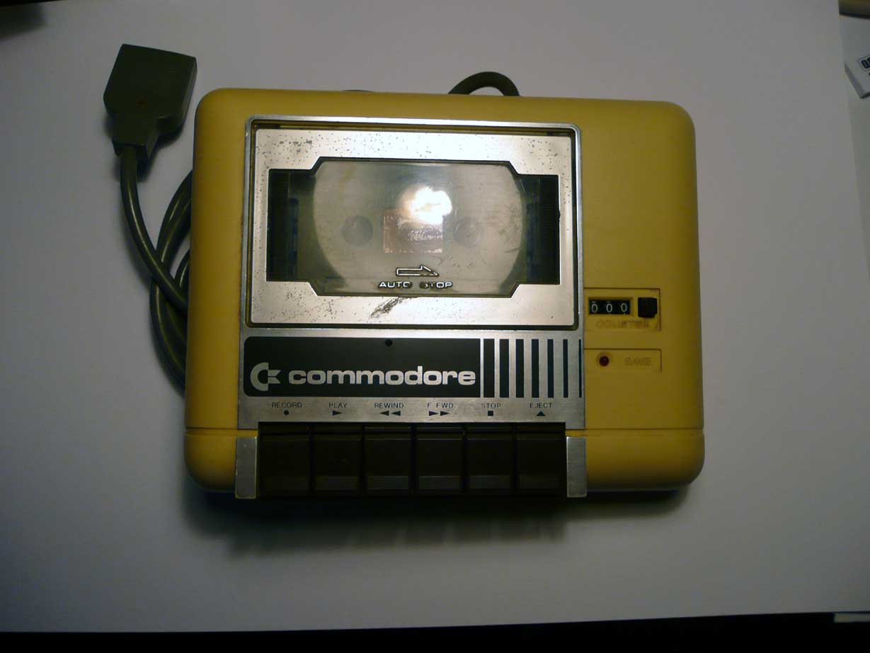
Bit og googling will find you some references. Basically it's making sure that the tape heads are perpendicular to the recorded data, to get the best high frequency response. There were fanct tape based programs that helped you optimise your C64 datacorder for best results. There is a cool trick \i've seen involving recording to a PC soundcard, and recodomg the results to allow you to stotr your prigrams on your hard disc. Never did any looking for this though - I only use tape as a last resort with old machine. When I recorded data from industrial PLC's, I always used my 'Walkman Pro', and decent tape. If anybody has a box of the old TDK SA or the Sony Chromes/Metals with the ceramic guides, I'd be willing to pay or swap things for them! Hoope it works for you. Mike
-
Datacorder and JB Weld posted today. You might need to dig up one of those azimuth alignment tapes. If you haven't come across that. let, me know, and I'll see what I can drream up.
-
I've got this one, over here in Bolton. Shall post it over with your JB Weld? I've never used it, so you can give me a small donation if it works, if not you have a paperweight. Note - I also have a (non commodore) 64 compatible floppy disc drive that needs an interface cable, and a big box of cassette and disc games etc, so it might be worth a visit.
-
There are quite a few companies selling add on touch panels for normal LCD's. The ones for smaller LCD's are quite realistically priced, (around £115 for a 17 inch panel and interface circuit). The interface is either USB or, on the older units, serial. Some of the older Point of Sale, (POS), terminals have a touch screen that emulates a serial mouse. These do turn up on ebay, often as part of a till system. For ease of use, stick to the 5-wire type of touch panel. It can see this type of app benig a good hack for an obsolete laptop, there are lots of those around, going very cheap, and the case could be hacked about to improve cooling. For most units, it's the death of the battery pack that writes them off. I'm trying to find a decent PCMCIA SCSI adapter, then I can make a dedicated panel type controller for 'Millenium' on my old Akai 3200 sampler Going back years, once I was doing work with light pens on the BBC micro. I managed to do a rotary control using a rotating 'mask' and two photodiodes, using a bright patch, programmed on the screen, as the light source. In those days, I had trouble keeping the interference from the scan coils out of the photodiode electronics, but the idea was that the controllers could be placed anywhere on the screen as the software required. It was aimed at special needs kids in a local school. Light pens are a pain to program for, and are now pretty well obsolete, though somewhere I still have an app that allowed me to make up patterns for a 'light grid' display, It was all light pen driven: you touched to toggle a light on or off, and there were pads to do things like mirror imaging/replicating, and to invert the whole pattern etc, there was even a 'save frame' pad. This meant that a whole pattern sequence could be designed that way, but I did find it gave me arm ache after a while.