

TheAncientOne
-
Posts
726 -
Joined
-
Last visited
-
Days Won
2
Content Type
Profiles
Forums
Blogs
Gallery
Everything posted by TheAncientOne
-
sammichsid - any way to create/edit SID files or extract their sounds?
TheAncientOne replied to cuca's topic in MIDIbox SID
Massively late to the party, but I have just been playing with the ASID player driving my MB6582, whilst laid up following a leg injury. I got the massive SID tunes archive from https://hvsc.de/ I noticedthat many will play fine via ASID under Windows 10, some only did the initial loop, this is probably because they are aimed at devices that directly drive the SID chip, not via SYSEX. I wanted to get at the 'Stardust' tune from the musc for David Whittaker's legendary 'Lazy Jones', (yes, the one made famous by Zombie Ntion using it in their track 'Kernkraft 400'). I decided I needed a SID file editor, and I found this thread in the process, so I thought I'd share the one I found, here. It looks a bit old fashioned, but works OK so far under windows 10. It is also available in PERL/TK script too. https://www.transbyte.org/SID/SIDedit_download.html It needs a SIDplayer and a hex editor to go with it. There are emulators etc available from the HVSC site, linked above. Hope this is of use to people. Wish me luck with the fileediting, this is all new territory to me Mike -
The last few years have not been good. A wonderful offer to do a masters degree, in 2013, came unstuck in a mess involving sciatica and the death of child for whom I was 'adopted family'. Depression followed. So it took a while to get going again. I've popped back in a few times, only to find I had no time. Now I'm making time and getting some of the stuff I began contructing into playable units. I've bultl quite a lot for other people in the last few years, to pay bills and keep going, like Psycox 'Syncussions', 'Jaspers', and various modules. I've done quite a lot of repairs, too. I even managed to do up a few 'donated' units for myself I've done a few MIDIbox units I can post pictures of: the GM5 and Nils' 5 channel version. My MB6582, which was the first MIDIbox project I finsished, in fact, and some test pieces. Now I'm about to use up one of my old core boards to make the old MIDI-CV, for my 5U system, I'm finally getting together. I have boards built, and the original AOUT board with it's Max 525s. So, todays small start was some banksticks. No major deal, a 1 hour project, from digging out some parts to looking at the end result. But it feels good. Something for my own gear again. MIDIbox feels different from kit building, more input is needed, and the sense of achievement is somehow greater as a result. So a quick 'hi' and a wave. And hopefully it won't be another 5 years between posts...
-
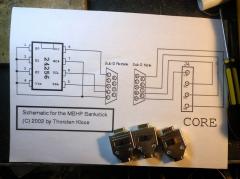
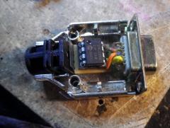
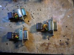
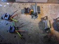
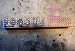
First MIDIbox stuff for a while. A very minor build: 3 banksticks for 2 upcoming projects. Note to other builders: don't do what I did and use the plated shiny D connector shrouds. it took as much time to make insulating plastic inserts as it did to solder them up!
-
-
From the album: Banksticks
-
From the album: Banksticks
-
From the album: Banksticks
-
From the album: Banksticks
-
From the album: Banksticks
-
From the album: Banksticks
-
From the album: Banksticks
-
I've just come across this thread, and seen a few of the ideas. First thought: MIDI is a current loop interface, specified at 5mA loop current, though often running a bit higher to give leeway for differing opto isolator input LEDs. The voltage is not really the issue. Changing the input of the 9090 is a bodge, it works fine with other sequencers - you will only get the same problem with other devices, especially those using older optos like the CNY series. The simplest solution to me, would be to reduce the value of the output resistors in the sequencer. Since there will always be a 220R in the input circuit of the target MIDI device, dropping the resistors at the sequencer end to 100R or 68R would get closer to the spec, and the max, shorted output current from the sequencer , (in case of a bad lead) would still be a fairly safe 16 - 25 mA. (standard short circuit current on 5V would be a round 11ma). Oh, and if anybody is thinking of termination impedance matching: try to remember this is low KHz speed, not RF, and the lower output impedance would actually help keep the pulses square.... (added 05/11/2017) The latest MIDI spec, (CA-033) MIDI 1.0 Electrical Specification Update [2014], suggests 33 Ohms from pin 4 to the 3.3 V rail, and 10 Ohms from the device output to pin 5. This makes for a short circuit current of 76mA, which I consider too high for safety on a microprocessor output. I think it's good practise to use an output buffer: if you are working live, a spare buffer chip can be kept in the toolkit. A spare micro module is not so easy. Just a few thoughts anyway Mike
-
MB6582 Rackmount Revisisted / Switch Matices
TheAncientOne replied to m00dawg's topic in MIDIbox SID
I was looking at something similar, though in a more industrial design. I wanted to do 'voice cards', as eurocards, and plug them into a backplane, allowing me to break out I2C for an AOUT NG and have space for a set of my 2044 filter cards. I intended to make a 'dumb' control surface, in a separate desktop case, and use proper CAN buffer chips to allow a longer cable between the sections. As a mark 1 version I was going to use the spare MB 6582 base board card I have to house the 4 voice PICs and their SIDs. I also thought about having separate illuminated buttons for wave selection etc., to avoid stepping through options in live use. For now, I am still learning how to drive my MB6582, so this went on the back burner. -
Despite being the 'Bulk buyer' and rare parts miner for this project, I didn't start building mine until last month! I did build an Adafruit kit; I got to the top of the list just after I started the bulk buys, and so got the kit and built it so I could test programmed processors, and check parts differences. I had a long layoff from electronic music work in general, due to a lot of problems in other parts of my world, but recently got back down to it. Amusingly, following a comment above, I have just finished my MB6582, (from Wilba's original boards), bar some ventilation holes in the case, and outputs for the MBCV-NG board to drive the 2044 external filter boards. The x0xen will be next - I've built up the power boards, and am just waiting for some multi-turn trimmers for the PSU setting - having built an Oakley TM3030, I can say with all certainty that they make setting that 5.333 Volts much easier. I am currently trying to find a local paint sprayer - i want to do the PT-10 case in silver to match the panels. I'll blog some details when I get a few minutes. I think I get the 'wooden spoon' prize for assembly time here!
-
It's alive! (Obligatory Mad Scientist Riff)
TheAncientOne commented on TheAncientOne's blog entry in TheAncientOne's Blog
I'm still house rebuilding here, but that will give me more space for the music gear when it's done. Analog tomfoolery will have to wait until I have space - I've got quite a few modules built, but no racks built yet. Glad to hear you're back in action too! -
It's alive! (Obligatory Mad Scientist Riff)
TheAncientOne posted a blog entry in TheAncientOne's Blog
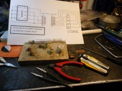
The missing socket arrived this morning. Full of will power I waited until after the days work was done before getting out the now rapidly declining box of bits. Socket in, C64 PSU tested, 9V tested good, so was ready to go. Small glitch until I realised that I had to change the core ID in MIOS Studio too, then all loaded smoothly. Fitted the 6852's one pair at a time, and ran through the sound banks, with a silly grin just getting wider on my face. Still got a minor bit of front panel work to do, (3 spacers came unglued), and a little bit of fault tracing - the mix out doesn't seem to be working, but all is good, and the only last bits I need are 4 knobs for the feedback pots. Now a lot of reading and learning to do. This thing is a small cased sound mainframe and I want to be able to drive it as it deserves.. Love the way my Korg Kontrol 49 keyboard loops up to a lot of the front panel controls too. So very grateful to TK and Wilba for this. -
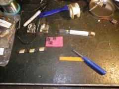
Still doing more stuff for other people than myself, but got another run at the MB6582. 3 parts to get, and it turns out that the ebay seller with the displays didn't ship what he thought. I have a 'plain, vanilla' black on green display, when I thought I was getting green on black 'negative'. I'll update once it's working. I had a reasonable idea for the display wiring, and put a single-in-line cable mount socket, (the kind you crimp pins to the wire, then insert into a housing), on the cable, and a 16 pin 90 degree pin header on the display. That means the fiddly display wiring only has to be done once, and I can change displays by simply plugging another one in. Pots for feedback were from Smallbear, and are neat, small Taiwan Alphas. I used heat shrink sleeving over the soldered pins to make the wiring more robust. I Used some salvaged 2 pin computer pin connectors, from old PC cases for the 5V connections to the power LED, and teh fan, and a 3 pin one for the audio out. I have done connectors for all the I/O and the control surface connections, so that main board could be removed safely, if I need to work on it. I hope to run it up next week, once my next batch of work is over.
-
[S] x0xb0x, MBFM built modules, PIC & SID boards, Waldorf Knobs
TheAncientOne replied to rosch's topic in Fleamarket
I'm interested in the Tabularasa board, I'm in the UK, any idea on postage? Thanks. Mike -
Same here - good to see you back!!
-
Yes - welcome back. It will be good to see some more of your stylish design work
-
Control surface PCB for 16 encoders/LEDrings Bulk Order
TheAncientOne replied to Fairlightiii's topic in Bulk Orders
Thanks very much Jerome - my boards were waiting when I got back yesterday. They look superb! -
Random construction pictures.
-
-
From the album: Prof's Build log
And it works! -
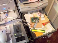
From the album: Prof's Build log
Mini production line. Burn on the left, MIOS load on the right. -
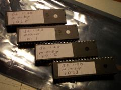
From the album: Prof's Build log
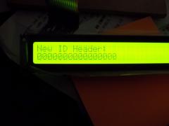
The results for tonight: MB6582 PICs burned and ID's set. -
Finally getting back to building music gear. Trying to do a bit every night; averaging 30% at the moment. MB6582, nearly complete. Must take the 'wooden spoon' for slowest assembly from the initial batch, but #31 is on it's way. Wired and tested the LCD, last night, only to find I'd mis-read an advert ages ago, and got CrystalFontz normal, (black on green) displays. Will go with it for now, but will probably go for Optrex when I get the chance, (they take way less current too). Chips burning session tonight. PIC4685 all burned, MIOS Loaded and basic test done. Reading through the notes, and using MIOS studio makes me realise just how much hard work TK and others have put into this. All went very smoothly. Started edits for my small SID box, having got the panel wiring laid out. I got lucky on ebay with some Densitron 'mini' 2x40 displays, which match some old 'Digitast' style switches I got with some scrap, so a 2x40, 10 button design resulted. I can see myself compiling that a few times before I get it right though! Mini production line And the results Tested - working showing Densitron 2x40 small display.
