napierzaza
-
Posts
442 -
Joined
-
Last visited
Content Type
Profiles
Forums
Blogs
Gallery
Everything posted by napierzaza
-
Okay, I tested my amps by grounding both inputs and measuring the output. The value of a working amp should be close to 0 volts. So far I found three amps were -6,-6,+7,-6 0,0,0,1 -6,-6,+7,+7 So I guess the second one is okay then? Has anyone else tried this method?
-
Aargh, No sound still, and the first pair of amps are getting hot for no reason. I tried to other amps and they're not working either. +-8 volts is okay right? I remember hearing that once and it works better with the transformer I have. Is there a decent way to test the Amps and or the rest of the circuit? I want to know if I need to replace the amps or just re-seat the smd.
-
Crap, It's strange as I only changed the PSU and nothing else, and that was tested.
-
I've been having trouble with my FM for some time, I had recently found out that my partially rectified current was not really working well (I thought it might have been adding noise, not to mention not being able to plug into a mixing board). So I decided to build a new PSU that used 9v regulators. Unfortunately though, I think that I blew my amps by just plugging in the 9+,gnd,-9 to my fm board; which ended up making my AMPs really hot. Sooooo, once my new board was built (& tested for voltage as it had been before it plugged it in) my FM no longer makes any noise, not even the scratchy noise it made before. Is just plugging in the bipolar supply a bad idea for the circuit? Does it somehow need the 5v to keep it from exploding or something? My CS and LCD and everything still come on and I can still upload midi.
-
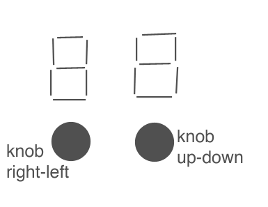
I was thinking of something like having two shift keys. They'd shift the entire matrix right or down and lock, so you can very quickly switch over to the next for tracks of the matrix or the next group of columns. They'd work like a caps lock so you can easily edit that section (you could have it function as a toggle, or even maybe just install a nice looking toggle switch for it to lock). It'd eve be cool to have 4 LEDs, and the active section would be the one that would light up for notification of where you are. To clarify: This only really makes sense if you plan on building a 4x16 array for track control. So you could basically move around your instruments and your 128 steps easier. Now that I see how many tracks and steps though, maybe we need two knobs (yes like and etch-a-sketch) so navigate the matrix. Possibly using number display LEDs might be better than a matrix? You should be able to have only one digit per direction. With 128 steps you get 8 shifts, and with 32 bars you have 8 different blocks vertically (assuming a 4x16 matrix).
-
I'm working on it. http://www.midibox.org/dokuwiki/doku.php?id=installing_gputils_and_sdcc_on_debian_linux
-
I got the Debian-Lenny source from the debian site.
-
It's not that I don't like the sound of a noise gate, it's just that I am not sure how much effort it will cost me in time/effort. I guess I can remove the noise in post anyhow. It doesn't sound terrible, I have two 6581s. In fact maybe I should mute the one that is not an R4 and see what it's like.
-
What a journey, I now know how to compile source code as they was not a debian package for etch. I guess I learned something new today! Thank you sir!
-
What's getdeb? Is that the apt for ubuntu? I tried apt, it's not there. Will look for a newer version. Thanks
-
Ewww, noise gate. Thanks.
-
Oh, So what am I looking at for compiling SID? gpasm-0.13.4 beta
-
I appears as if the 18f4685 does not work with gputils and sdcc. Is there anything I can do? Using up-to-date versions of SDCC and Gputils in Debian Linux. I compiled Midibox FM successfully before (different processor). nmcdavit@killerwhale:/local/mios/midibox_sid_v2_0_rc25$ make rm -rf *.cod *.lst *.err rm -rf *.hex gpasm -p p18f4685 -I./src -I ./include/asm -I ./include/share -I ./modules/j5_io -I ./modules/aout setup_6581.asm Didn't find any processor named: p18f4685 Here are the supported processors: eeprom8 gen p10f200 p10f202 p10f204 p10f206 p12c508 p12c508a p12c509 p12c509a p12c671 p12c672 p12ce518 p12ce519 p12ce673 p12ce674 p12cr509a p12f508 p12f509 p12f629 p12f635 p12f675 p12f683 p14000 p16c5x p16cxx p16c432 p16c433 p16c505 p16c52 p16c54 p16c54a p16c54b p16c54c p16c55 p16c55a p16c554 p16c557 p16c558 p16c56 p16c56a p16c57 p16c57c p16c58a p16c58b p16c61 p16c62 p16c62a p16c62b p16c620 p16c620a p16c621 p16c621a p16c622 p16c622a p16c63 p16c63a p16c64 p16c64a p16c642 p16c65 p16c65a p16c65b p16c66 p16c662 p16c67 p16c71 p16c710 p16c711 p16c712 p16c715 p16c716 p16c717 p16c72 p16c72a p16c73 p16c73a p16c73b p16c74 p16c745 p16c747 p16c74a p16c74b p16c76 p16c765 p16c77 p16c770 p16c771 p16c773 p16c774 p16c781 p16c782 p16c84 p16c923 p16c924 p16c925 p16c926 p16ce623 p16ce624 p16ce625 p16cr54 p16cr54a p16cr54b p16cr54c p16cr56a p16cr57a p16cr57b p16cr57c p16cr58a p16cr58b p16cr62 p16cr620a p16cr63 p16cr64 p16cr65 p16cr72 p16cr83 p16cr84 p16f505 p16f54 p16f57 p16f59 p16f627 p16f627a p16f628 p16f628a p16f630 p16f636 p16f639 p16f648a p16f676 p16f684 p16f685 p16f687 p16f688 p16f689 p16f690 p16f716 p16f72 p16f73 p16f737 p16f74 p16f76 p16f767 p16f77 p16f777 p16f785 p16f818 p16f819 p16f83 p16f84 p16f84a p16f87 p16f870 p16f871 p16f872 p16f873 p16f873a p16f874 p16f874a p16f876 p16f876a p16f877 p16f877a p16f88 p16f913 p16f914 p16f916 p16f917 p16hv540 p17cxx p17c42 p17c42a p17c43 p17c44 p17c752 p17c756 p17c756a p17c762 p17c766 p17cr42 p17cr43 p18cxx p18c242 p18c252 p18c442 p18c452 p18c601 p18c658 p18c801 p18c858 p18f1220 p18f1320 p18f2220 p18f2320 p18f2331 p18f2410 p18f242 p18f2420 p18f2431 p18f2439 p18f2455 p18f248 p18f2480 p18f2510 p18f2515 p18f252 p18f2520 p18f2525 p18f2539 p18f2550 p18f258 p18f2580 p18f2585 p18f2610 p18f2620 p18f2680 p18f2681 p18f4220 p18f4320 p18f4331 p18f4410 p18f442 p18f4420 p18f4431 p18f4439 p18f4455 p18f448 p18f4480 p18f4510 p18f4515 p18f452 p18f4520 p18f4525 p18f4539 p18f4550 p18f458 p18f4580 p18f4585 p18f4610 p18f4620 p18f4680 p18f4681 p18f6310 p18f6390 p18f6410 p18f6490 p18f64j15 p18f6520 p18f6525 p18f6585 p18f65j10 p18f65j15 p18f6620 p18f6621 p18f6627 p18f6680 p18f66j10 p18f66j15 p18f6720 p18f6722 p18f67j10 p18f8310 p18f8390 p18f8410 p18f8490 p18f84j15 p18f8520 p18f8525 p18f8585 p18f85j10 p18f85j15 p18f8620 p18f8621 p18f8627 p18f8680 p18f86j10 p18f86j15 p18f8720 p18f8722 p18f87j10 rf509af rf509ag rf675f rf675h rf675k sx18 sx20 sx28 make: *** [setup_6581.hex] Error 1
-
I got my SID Making sound. I expected maybe a little bit of a hum or something, but for some reason I get noise in the background. But it's not a ground loop, it's a really low volume tone coming out of the SID, one which is still modified by the the pitch bending wheel on my keyboard. I haven't modifed the patches so it's not foolish sustain or anything, and every patch does it. It's exactly like a very low volume of the same tone that I would have been playing. It's even there on boot-up before any note messages have been sent. Has anyone else had this??
-
Whatever man, Macs are awesome. Yes, it worked, though the possibility of using the old holes was still nil. I have a bunch of caps soldered on at 45 degree angles. But hey, it works.
-
Woooooooooooooooooooooooo Thanks again guys IMG_0014.JPG IMG_0014.JPG
-
Gas powered iron is A++, but I won't be using the holes on the board, little ugly!
-
Thanks for the suggestions. I have to work with non-lead if it is non-lead? I thought they would mix and make the non-lead solder more pliable. I will check how many watts my iron has. But I think it should be a lot. If not I am borrowing a friend's gas powered one.
-
Actually I am taking the job of a slave laborer! I already pulled off about 5 caps and often enough I am not left with enough leg to attach to it. So it's nto a solution for the ones I already did, or the ones in the future that it will happen to me. It might be the central ground plane, as you mention, EXCEPT that I can't even hardly get the solder around the pin liquid enough. It's still tacky after touch a 400Celcius iron. I think I go out and buy some flux :-\
-
Actually I was trying to tilt the off the board by heating one pin then the other. I busted a cap (hehe) doing this because the legs just gave way. I then used pliers on the remaining pin and applied heat and pulled. I still couldn't do it. I tried soldering to the stump, IT DOESN'T WORK! My beads just don't stick to the pads! Their like the anti-solder pads or something. Do I have to somehow clean the board first? It doesn't appear dirty, or to have any sort of coating, but I don't know how it's rebuffing my efforts like this. How are they servicing this stuff?
-
I recently acquired a G5 iMac that was having issues. I checked inside and happily realized that the capacitors were shot in the unit, which I could easily fix myself. I had already done this to an older eMac that I was also broken down with no issues whatsoever. I even harvested the caps from elsewhere and it cost me nothing. So, I ordered the replacements and I got them in the mail today. So tonight I giddily tried to remove the caps and ... no dice. They're stuck, I even put my iron up to 400 degrees C and I couldn't even get the caps to budge at all. I even tried ripping the caps from the board and realized that I couldn't even stick the caps on sideways onto the pads that are left. So it looks like it's using some kind of leadless solder. Does anyone have a suggestion to remove stuff like this? I never encountered such a large, through-hole part that was so impossible to remove. I can't even get it to budge one bit.
-
You're a good man sir, thanks.
-
Wait, am I changing the ac lines on the primary 120vAC side or the secondary side? I was just thinking about it and realized that I'm not sure if it would matter if I switched the secondary connections.
-
ACtually now that you mention it, I guess it is already more or less grounded to the case. Hrrmm, anyhow, will switch around the PSU inputs today just to see. Much appreciated.
-
Okay, thanks. I will give that try. But I guess I still can't ground the common to the case? Also, if anyone does have a schematic for a bipolar circuit using either two transformers or a center-tap, I'm all ears.