napierzaza
-
Posts
442 -
Joined
-
Last visited
Content Type
Profiles
Forums
Blogs
Gallery
Everything posted by napierzaza
-
I just moved apartments and was shocked to see that the LCD screen for my under-construction Stereo SID was smashed. I'm wondering where the best place for buying a 20x2 LCD would be. I'd like it to ship to Canada really cheaply if possible! I had all my parts together and this is a big set-back if it's going to cost 50$ for me to get my SID going.
-
I really just want to minimize interconnections and panel mounting because I am making it all by hand. Thank you very much!
-
http://www.futurlec.com/LED/LCD40X4BL.shtml Would this work with the SEQ V3? I'd be interested to not have to wire two separate screens.
-
Okay thanks, I think I might not go with a joystick then. I appreciate the information.
-
Oh my, yes, correct again. Sorry sorry sorry. I've lost much sleep. So then... Is there a way to have TWO of J5 work as AIN and the remaining 6 work as a functional DOUT?
-
This is correct. I'd like to install a joystick into my box. Assuming 4 AOUT connections, or two for each pot. After that I need the last 4 pins for DOUT for some LEDs for the Filter module.
-
Thanks very much for the answer Thorsten. So does this mean that I can add one Pot to J5 and then Assign it dynamically through the CS menus? This is good. Is there anyway to activate only 4 J5 pins for AOUT, and use the other for for DOUT?
-
Okay, so I've been thinking, and possibly having a LFO or Filter joystick control might be very interesting. However I'm getting a lot of static on my searches because most of the stuff about it are from 1.7 or lower SID firmwares; and from what I can tell it's remarkably different now. I basically have one joystick I might use for LFO(because I have no panel controls for that) or the Filter (maybe replacing some of my panel controls?). Does anyone have any pertinent SID 2.0 information? EDIT: from what I can tell there are options in the setup_*.asm for different AOUT options. However I noticed that everything is separated. What I'd like is to have one joystick, and let's say, oscilator select buttons to shift what it's controlling. That way I might even be able to control LFO, OSC, and Filters by including a joystick and the selection buttons one the panel instead of 12-ish sticks.
-
So you can use J5 for DIN as well? How useful is using it for analog inputs? I was thinking of possibly a joystick but there isn't much on that in the documentation. Has anyone been very successful with this? I'd like to know how useful it might be.
-
Argh, you're right, I can't find it. Perhaps I was remembering that it said you could use the 2x16 and then saw the really small hole in the panel design layout.
-
Sh*t. Thanks.
-
Oh, well the SID page said that it was default for 2x16 and the default items were 5. Anyhow it doesn't matter, I didn't really think I need more than five anyhow. The front panel uses a much smaller LCD from what I can tell though, way shorter than mine. Thanks.
-
I only have a LC 2x20. Should I bother changing the number of items to 7 or is 5 enough? I'm not sure I want to bother with it but I've never seen the interface. I don't have anything other than a 2x20 though.
-
Sorry, DOUT.
-
So do I need to affix 220 Ohm resistors if I'm using J5? I hope not, I'm out!
-
I guess it makes me lame for thinking this might be a bug!
-
Okay, going through all the pin assignments. What the devil is with this: <code> ;; additional CS encoders ;; SR Pin Mode ENC_ENTRY 3, 0, MIOS_ENC_MODE_DETENTED2 ; Osc delay/transpose/assign #1 ENC_ENTRY 3, 2, MIOS_ENC_MODE_DETENTED2 ; Osc attack/finetune/assign #2 ENC_ENTRY 3, 4, MIOS_ENC_MODE_DETENTED2 ; Osc decay/portamento/assign #3 ENC_ENTRY 3, 6, MIOS_ENC_MODE_DETENTED2 ; Osc sustain/release/assign #4 ENC_ENTRY 3, 8, MIOS_ENC_MODE_DETENTED2 ; Osc release/pulsewidth/assign #5 </code> It says that there is a 8th pin for that SR? Looking at it I believe that it's showing only even because encoders take two pins to function. So I think this ASM is implying that this is a 10 pin encoder. It says there are only 8 pins though... correct?
-
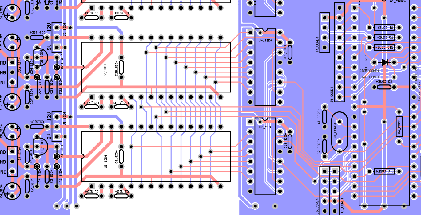
Thanks for the verbose answer Wilba. I really appreciate it! I made my own double-PCB based on your designboard, and so my SID is on the audio ground. So far the design I made is going well, just trying to correct any mistakes I might have made before actually putting my 6581s inside. I don't want to damage them. I'm using two transformers for my power, so the only connection between 12v and GND is through the SID. I was wondering whether something bad wound happen though considering that it's taking 5v and not grounded to the same level. I'm glad to hear that it will not be a problem, I will remove my ground pin jumper!
-
Herm, okay, I'll have to do this. I have two seperate transformers so ultimately I guess there is no really appropriate ground connection.
-
So... 14 is the regular 5v ground... and which is the audio ground? I was told to seperate the 12v and the 5v ground, but I don't know where they should actually go. Or is it that the IC is completely 5v. But the the audio is 12v? If I have two separate power supplies and wire it like that, there should be no issue?
-
Okay, so if the SID has a 5v, and a 12v (or 9v) input, AND two grounds... Which ground is which? I have no seen any info on this but I believe Wilba suggested having them seperate. In is design they are together though: Can anyone shed a light on this?

-
I've been hijacked! Can someone post a link for control surface schematics before he posts more photos?
-
Your setup is pretty low key. You had to use a DIX4x? This is interesting, I may want to do the same. BTW, I don't believe I see any links to wiring schematics. Many, the panels that you guys have made! I can barely afford to get the actual hardware together, much less a shiny panel
-
Yes, well I have the 7812 on my SID board and I assume that's adequate enough! Looks like it's working, but I haven't checked after my 7812 yet as I'm still in the assembly phase. But I will most definitely be checking before plugging in my SIDs.
-
I have made a SID that is comprised of one CORE and two SIDS attached to it (in the same way that Wilba wired two SIDS together on his unit. I have looked at the different control surface options and am wondering, what do I really need for my unit? I appears as if Control Unit C is too complex for me, and B is more so about if you have multiple slaved SIDs. So if I want a decent control of my sid does surface B offer me any benefit? Also, I can't find any schematics for wiring on the site. I found this one, but am unsure which Step it is. Also, does this work with SID v2? http://ucapps.de/midibox_sid_cs/2x20_enc_multi_w_j5.pdf