m00dawg
-
Posts
1,404 -
Joined
-
Last visited
-
Days Won
16
Content Type
Profiles
Forums
Blogs
Gallery
Everything posted by m00dawg
-
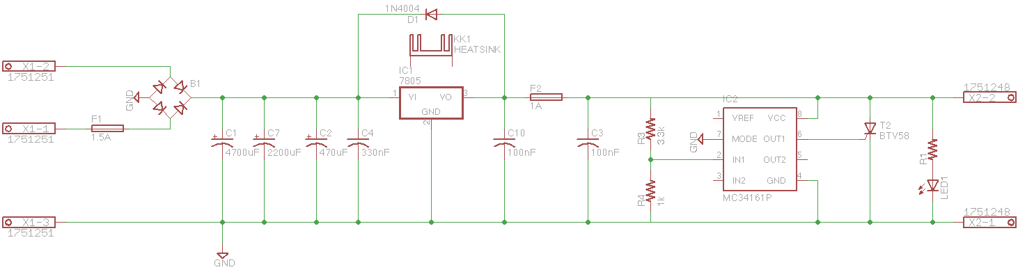
I think I finally figured out how to use the MC34161 along with the clamp. You can do some cool things like having under and over voltage thresholds but I have used it for over-voltage only. I would guess a discrete circuit that doesn't use a voltage divider is probably a slightly better design. I'm not sure how the IC compares to solutions that do use resistors, but at least I can swap the chip out if it fails. I removed the avalanche diode since the IC does basically the same thing. I might put it back so it handles small voltage spikes while the IC handles larger ones, but I'm not sure. Anyways here's the new schematic.

-
Looks like the application is mostly the same, although the newer chip has some nice features - and happens to already be in Eagle so that's a bonus :) Only concern I have is the accuracy of the voltage divider, especially with 12VDC. Can get high precision resistors, but still curious what the percent error might be. I suspect small enough to be useful. Using a voltage divider also means those only need to be changed to handle different voltage inputs, which is nice.
-
Probably so :) I'm actually looking at the ON MC34161 family of chips Technobreath mentioned in his crowbar circuit design gallery (linked up above) to see if I can use that to help with a crowbar. Pretty neat in that it can alert to over and under voltage, but I haven't quite figured out how to use them yet (and I don't know how to power it ;P regulated or otherwise).
-
Ah that makes sense. Though 300W is a lot. I think for my design it would be closer to 50-100 max, although that's still quite high for such a small device, noted. Still, for what it does provide, it's pretty easy to just drop one in where it is. Having both does make for an interesting situation though since now I have to make sure one triggers in certain cases over the other. *scratches head* Well looks like there is more research to be done! Thanks for all the helpful info!
-
20MHz is enough to look at signals for audio applications though, no? I guess once you have to start looking at logic of fast switching components it might start to show its age? Mostly for me I need one for PSU stuffs, although I guess I could see it being useful to debug sick chips too.
-
Hah! Agreed! I guess for a 5V supply I can use a battery pack just as easily to hit 6V but I'll need something more variable for my 9V and 12V supplies. SmashTV recommends this and it looks pretty much Win for the price, but I may have to settle on a used old-skewl one for a little while. Prices went up on eBay since the last time I looked though :/
-
Aha! Guess I need one of those as well as an oscope :P
-
Indeed! Worthy of testing anyway. Curious - how did you end up dumping 6V onto your circuit to test the crowbar?
-
Worthy of giving it some board space just for the chance is my thought :) Wish I was able to find a good comparison between the Avalanche Diode as I have it versus a crowbar. The two seem the same but Wikipedia suggested that Avalanche Diodes can react a bit faster.
-
I haven't seen the diode used as much for non-polar supplies but I have seen it used for the purpose I explained, including some documentation from a few college level lab courses so I think there is some purpose there for it. I tried busting a circuit simulator to see if I can determine what's going on. Without a way to emulate a fuse it was hard to fully validate it but I was able to break the simulator a few times with it so I think it works ;) From what I have read, TVS tends to be an optional replacement for a classical crowbar design - the two are meant to do the same things it would appear. SCRs are similar (looking at the Wikipedia article you sent, they both involve avalanche breakdown). I think I was confusing these with thermistors so I'll have to look at those a bit more I think. Either design seems reasonable since they are both meant to control over-voltage (which should never happen unless there is a component failure?) As far as cost of the protection, it's a pretty inexpensive addition so I think it's good to go ahead and put it in. For cases where failure is less of a concern, one can just back off on the tolerances to avoid accidental tripping. But for a couple bucks worth of parts, it's WELL worth it for the cost of those hard to replace chips like SIDs or the OPL3 chipset. EDIT: Oh I forgot to ask - I was trying to look at some IC-based designs and wasn't able to find much when looking at Mouser. Do you have any suggestions for some reference designs?
-
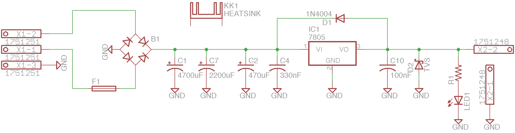
I started reading through epic thread again (which really should be sticky, I think) while specifically looking for circuit protection techniques. A crowbar circuit was discussed but I also ran into one design that put a diode between +V and GND after the regulator instead. After reading up on things (here, here, and here, see Jay2's comment to name a few), I think I have it figured out. Mouser has an entire section devoted to TVS Diodes and it looks like they have fairly specific voltage targets. So I think this is the thing to use over just a 1N4004 or Zener diode? I have seen designs using just an 1N4004 and according to what I have found, using one may work, but could destroy the diode in the process as they are not built to sustain avalanche breakdown? I also want to make sure I understand things right, during normal operation, the TVS diode stops current flow to ground but since current is now flowing through (like it would be in-line), there is no voltage drop on the supply. If the breakdown voltage is reached, current explodes through the diode in the opposite direction, causing a short to ground which then should blow a fuse. One thing I read is that avalanche diodes are also used in situations that need to generate noise. I assume that is only when the breakdown voltage is met or exceeded (and that they do not contribute adversely to noise otherwise)? Anyone have any thoughts? I don't want to just stick a random diode somewhere without knowing the right kind to use and its intended purpose. The designs that use a 1N4004 in this way confuse me given what I have read about those diodes compared to TVS / avalanche diodes. Attached is my current design with this in use. My plan is to make this a sort of template board that I can use and plug in various values for the resulting voltage and load. It's sort of the basis for a semi-modular PSU design I am working on for my band's live stage rack. Since my requirements can change as I add more components, trying to have something modular (at the expense of space) is worth it over trying to design one big PSU that has all the voltages I may ever need. Or so is the idea. Thoughts or suggestions?

-
Aha, gotcha.
-
True but you still have to have a reasonable input voltage into the regulators. Using Schottky diodes with LDO regulators just means the output from the transformer can be closer to the desired DC voltage, if I'm not mistaken. So you still have a heat problem if you try to feed 15VAC into a 5V regulator.
-
Right but the heat is being dissipated over a much larger area. I used 2 resistors to pull down the voltage and that ended up being an area around 4x2cm. Much larger than trying to pull all that heat out of just the regulator a quarter of the size. I had a heatsink on the regulator too, of course, but it didn't have to be near as large doing it this way and added some flexibility. But I still think that using a transformer is still the best option.
-
A transformer would be the way to go, but an alternative to running all that power through the regulator is to use power resistors to step down the voltage before it gets to the reg. I did that in my first MB6582 PSU and it worked quite well. As far as switch-mode versus linear, I say right tool for the right job. Switchers will likely continue to gain in popularity, and that's generally a good thing. But some applications will always demand linear. The latter is also a lot more simpler.
-
I don't think the mixed output on the MB6582 is crap at all. It's just passively mixed so it's a bit more quiet compared to the direct outs. That plus you can't control the volumes of each output or anything. But for what it is, works great! I don't think I would use it for recording but apart from that it's a good every-day output and is certainly convenient if you don't have 4 stereo inputs on your audio device to dedicate to all 4 SID pairs.
-
That thread is perhaps my favorite all time thread on the MidiBox forums. Pretty much everything you need to know about basically any PSU option is convered in there. It IS a long read, but man it's so educational and I still reference that thread on a semi-regular basis. I actually think that thing should probably be a sticky thread.
-
Yeah I may still opt for something else as the DB9's are way more expensive than they should be. But I opted to try the PCB mount options just to see how that goes. The new design avoids cabling between the main board and the control surface board (much like a sammichSID or sammichFM) and that's really nice. The catch is I didn't find much else to use other than a DB9 connection so I'm going to try that first for the prototype and see if that can be improved on. I can't use multi-conductor or CAT5 cabling for the other end because it's part of an existing cable I cut and strip (the other end is a proprietary connector that cannot be easily sourced). But it's about the thickness of a CAT5 so good to know those should work with the Conxall.
-
For what it's worth, I haven't been able to get the MBFM CTRLR talking back and forth with Ableton Live either.
-
Always a treat, these are Hawkeye! Definitely dig the more classic sounds. I think the part around the 4:00 minute mark was my favorite. Has that nighttime something is about to go down in the city kinda vibe.
-
:) I'll check that out! Seems pretty straightforward to add things. Only other issue is that changes on the panel weren't being sent back to Live as MIDI events so I'll still need to figure that one out.
-
Well, since I don't have MBSEQ yet, I played around with Live more and noticed if I set the Bank, Sub-Bank, and Program all to the same value it works. No idea why :P
-
I finally fixed the display on my MBFM and gave this another spin. I am curious as to if there is a way to send a patch change even using the interface? I wasn't able to find it, although the converse works (pulling in the current patch from MBFM). That functionality would be nice if I was able to record the bank change from CTRLR into a MIDI/automation track in Ableton Live (thereby having a nice work around for Live's own poor handling of bank/patch changes).
-
There is and that should work just fine. You may get some benefits by making your own 9V PSU off of the 12V rail and supplying the boards with 9V directly. You will save a bit on parts, but mostly it would give you more room to handle things like circuit protections (the diodes above the regulators in the schematic Altitude provided for instance), heat management (heatsinks) and extra filtering caps. But that is generally optional.
-
Ah I was thinking about these a bit. Curious - how goes it with soldering together a cable-side connector? I will have to use existing cable (the other end is a custom adapter I can't easily source by itself). I thought about using DIN connectors but I wanted something a bit further removed from MIDI (to avoid confusion). EDIT: Hmm now that I think of it, I just realized that instead of mounting the baseboard to a rack shelf, I can just mount it behind the control surface board. So now I'm debating on a PCB mount solution for the panel-side connector, likely still on the control surface board (with male/female headers behind it in a sandwhich sort of like sammichSID or the Arduino stuff). Then I can mount the main board using the corner screws of the control surface board. Thing about is that I need connectors on the panel side that aren't too deep (either panel mount or PCB mount). Hmm...