sineSurfer
-
Posts
346 -
Joined
-
Last visited
-
Days Won
3
Content Type
Profiles
Forums
Blogs
Gallery
Everything posted by sineSurfer
-
hehe, not that easy, in the first attempt I got half of the wires wrong ;D thanks Wilba!
-
Hi, so far I have tested both smashTv's Core and 2 mbSID modules ->one each time, all working fine. Next step is to connect all together, that is 1 Core controlling 2 mbSid= stereo mbSID. I'm planning to make an extra board with all the modified wiring and IDC connectors(like a jumper on steroids hehe) to avoid funny pin wiring so I can keep using 1 to 1 wires on the Core. And I need to ask if the "disconnect D0-D3 on the LCD" is necessary for this config.(only 1 Core, no plans for more) maybe I can skip this one on the extra board? thanks!
-
mbSID alternative PSU and expert advice needed
sineSurfer replied to sineSurfer's topic in MIDIbox SID
thanks for the so informative answers yogi!!!, next psu will be easier ;D btw, going this way I got the parts count to be the same as on the optimized c64 psu schematics(only the reg. is different), and it seems like a good replacement for the c64 psu, only time will tell :) i'll post some pictures later. -
mbSID alternative PSU and expert advice needed
sineSurfer replied to sineSurfer's topic in MIDIbox SID
Update: In the end my C64 psu 9AC part died, then I tried to open it, wasy task but biiiig surprise inside the psu enclosure is filled with some hard substance, like epoxy glue, including the broken fussible >:( So I changed plans once more and bought a transformer labeled as 18v/500mA AC with central tap, multimeter reads 10v AC from 1 of the outer wires + central tap or 20v AC from the 2 outer wires, no central tap. I went with the first option and the weird thing is after the rectifier the multimeter reads 14.5 DC volts!? which turns out to be enough to feed the mbSID module from smash with the 6581 chip so I just added a 7805 to get the 5v for the core and everything worked fine and without any noticeable noise, of course I added the caps too. so the only noise is from the 6581 chip, but that one goes away with a gate:) But I'm wondering if I'm not pushing too much the 7805 with the 14v? spec sheet says it will take it... but it gets hot, should I get the biggest heatsink I can find? is possible for the 7805 to pass the full 14v if it gets damaged? a fuse between the 5v wires and the core can help to protect the core? -
So... Wilba, how about having just two banksticks but wired as A0 and A7. one for patches, one for ensembles?
-
Need Updated PCB Layouts (CORE_R4, AIN_R4 ...)
sineSurfer replied to yankohurta's topic in MIDIbox Documentation Project
I went thru the chat to speed things up and got my kits 2 weeks later in Mexico, also, I paid for the EMS service, it costs more but you get the stuff always.;) -
check this design, from Yves Yusson: http://www.modularsynth.net/viewtopic.php?t=94&postdays=0&postorder=asc&start=1340 there is a link to download the ready to print pcb, and explanations for the transformers, I built it using two transformers to feed the +15v and -15v needed it works fine, just change the regulators for the 7812 and 7912.
-
mbSID alternative PSU and expert advice needed
sineSurfer replied to sineSurfer's topic in MIDIbox SID
Hi dj3nk... yes, I been reading thru almost every psu related thread here in the forum. Well, so far it looks like the atari psu won't do the job for both voltages, it drops to 9v when loaded, i'll have to use the c64 psu until I can find or build a suitable replacement ;) -
mbSID alternative PSU and expert advice needed
sineSurfer replied to sineSurfer's topic in MIDIbox SID
thanks a lot for that schematic warland, I had a talk with smashTv and now i'm not convinced about using the Atari psu after all, but will see when I finish with all the soldering on the modules. btw. I forgot to tell i'm using smashTv's modules, Core already has 7805 and SID a 7812(for the 6581 sid) so I guess whatever extra volts there will be handled by the regulators on the modules, is this right? maybe the 13.5v is too low to drive the 7812 on the Sid module? I'm wondering if leaving duplicated regulators would give me even less voltages: 7812 and 7805 on the input stage plus the 7812 and 7805 on the modules or should I skip the regulators and leave only the filter caps to filter the noise? thanks for the help! -
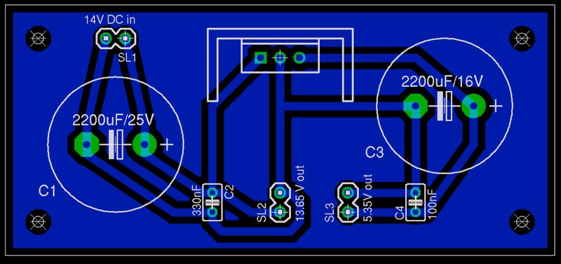
Hi everyone, as my limited electronics knowledge comes from the web and basically I'm just learning as I go, some expert advice would be apreciated. I found in my trasure chest an old Atari 5200 psu labeled as DC 11.5V at 1.5A, the multimeter shows 14V out of it so I figured it could serve as a c64 psu substitute for my mbSid about to be built. And after some tests and failures following the optimized c64 schematic I got a modified version that outputs 5.35v and 13.65v. Are this voltages safe for 1 core and 2 sid modules and 1dinx4? I did the schematic and board on Eagle just to be sure (probably i'll build it on veroboard only), can anyone check if its all right, or any possible shortcomings I may be facing going this way? I would like to be as sure as possible before commiting to this solution. thanks in advance!


-
thanks for the offer TheProf, I wonder how much could cost a tracked package from UK to Mexico city though. good sources!, thanks! ;D, the intention was to have those knobs available on the left side of the pond with the reduced volume and shipping cost if any, that is if there is enough demand from the mb808ers... which seems to be null so far
-
looks good, reminds me of those russian analog synths!
-
Algun midimaniaco con experiencia con el modulo usb
sineSurfer replied to un.diletante's topic in Español
Que tal, saludos desde México, según lo que he leido al respecto(cero experiencia), el modulo USB si te permitirÃa cargar el MIOS, pero es un modulo difÃcil de armar y da algo de problemas al configurar en Win, parece que en Mac va bien. acá la página en español:http://www.ucapps.de/mbhp_usb_es.html no te resultarÃa más fácil ver si algún amigo tiene computadora con la interfaz MIDI?, sólo se requiere cargar la aplicación una vez, salvo que vayas a escribir tu propia versión entonces si necesitas estar cargando los cambios. -
P301 for tempo and "instrument" encoder too. 8) Nebula: please ask for the P670 knob model too, black knob with orange or white pointer, that combination alone could add at least another 38 extra knobs to the order for each mb808er joining the group buy!
-
cool!, i'll take a bag of those (black/black). I'll draw some attention to this thread on the mb808 forum too to increase the # of knobs to order :)
-
change that to: "only for US citizens crowd, living in the US, and possibly only if the order is big enough" Just tried to buy some of those screws from them to be delivered to Mexico, first answer: "Thank you for contacting us. Due to the ever-increasing complexity of U.S. Export regulations, McMaster-Carr has decided to only accept international orders from a few of our long-established customers, so we cannot accept your orders." then I asked if I could get the order shipped to a US address, second answer: "We are concerned with our products' final destinations so, unfortunately, we will not be able to accept your orders even if you ask us to ship them to a domestic address. Please accept our apologies." what the f$%&k is wrong with this McMaster people?
-
and where is the noise? ;D your mb6582 looks good jimp, but you really need to get rid of all the green on it :) did I asked where is the noise?:P
-
yes, I found out that too :(
-
I would too, although I like more this knobs:


-
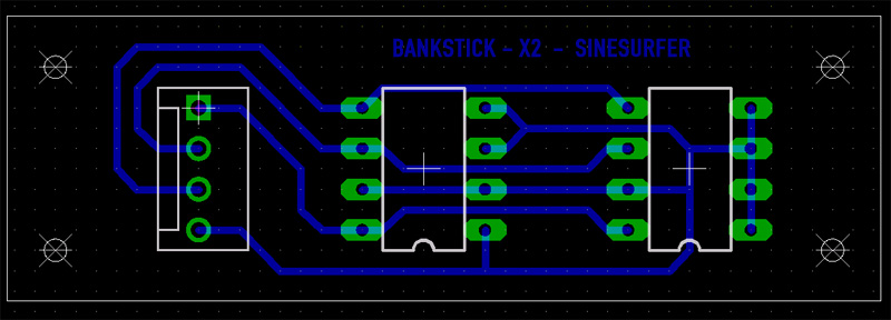
BankStick X2 ready to etch, can anyone verify the layout?
sineSurfer replied to sineSurfer's topic in Testing/Troubleshooting
Yes, noticed that error too, hard to read that tiny schematic ;D nice examples there!!! still a lot to learn for me, the good thing is that I'm getting to know the program :) i'll guess it will be hard to improve on your design, but i'll come back with some more, thanks! -
Hi, I thought about training myself tu use Eagle app doing a BankStick for 2 chips, and then some more, like 1, 2, 4, 6 ,8 to cater for anyone needs, easier to etch than stripboarding, at least for me ;D So, can anyone more experienced than me(almost everyone here I guess)tell me if I got this one right please?

-
Ok, confess now Wilba!!! you where the owner of a commodore cervice center back in the day and built the mb6582 just to get rid of all your overstocked parts!!! ;D ;D ;D
-
mm, I thought I had included myself here before... anyway, I'm in for 1 kit, I hope is not too late :-\
-
And still you have a good deal on taxes on UK, here in Mexico if the declared value is more than US $100 you get to pay 38% of the total value including shipping costs, not funny.
-
U.S. BULK ORDER - MB-6582 Knobs from ALBS (the "Waldorf" knob)
sineSurfer replied to bugfight's topic in Bulk Orders
got my knobs today, thanks Pimp!