

baconjuice
-
Posts
26 -
Joined
-
Last visited
Content Type
Profiles
Forums
Blogs
Gallery
Everything posted by baconjuice
-
I think i see what it is you are after here. The problem is that the C=64 brick does not output 14 volts. It outputs 5 volts DC and 9 Volts AC, so somewhere on your circuit you will need to convert that AC voltage to DC for your sids. Does that make sense? Another option, and probably the easiest imho, is to supply your circuit with a 12V DC power supply and include both a 7805 for the core and logic chips and a 7809 (6582/8580)or 7812(6581) for the sids. Hope that helps...
-
Los projectos de BaconJuice...
-
-
From the album: baconjuice - It's Bacon!
-
From the album: baconjuice - It's Bacon!
A little blurry but you get the idea. -
From the album: baconjuice - It's Bacon!
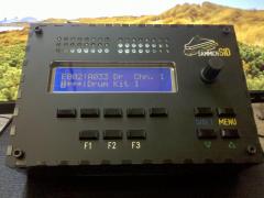
This guys is so portable it goes everywhere with me. -
I've been wanting to do this with my sid as well. I was planning on using a cold cathode light like the ones used in computer cases. They are cheap, run on 12v and usually have adjustable brightness. I have one that I salvaged recently and it even has a mic so it can light up with the music. Only drawback is that they use an inverter and that might introduce some noise into the audio but I think that all depends on placement besides, that problem exists with using EL stuff.
-
hello Toneburst, Not sure if this is what you are experiencing but I've had this problem before on pads that are attached to a ground plane. the ground plane acts like a heat sink so the pad doesn't get hot enough for the solder to stick to it. One thing that has worked for me is to turn up the heat and put a little more of the iron on the pad rather than the component. Try not to leave the iron on there too long as high heat can damage some components. As far as being slow with the soldering goes, I wouldn't worry about it. Quality is better than speed when it comes to this. baconJuice
-
Hello Rutger, Great job on the editor and thank you. Just as an additional data point, I was also having the same problems as Imp and Vout using my usb to midi interface (M-audio Uno and Keystation 49). I then connected to my desktop with built in midi (joystick port to midi) and the program worked fine. I remember when I first finished my MbSid, I was having problems with uploading the patches using Midi-ox and TK suggested that I increase the output buffer in midi-ox to work with my device (I don't remember what the default was but increasing it to 2048 worked). I wonder if there is a similar issue happening here? Anyway, that conversation is here: http://www.midibox.org/forum/index.php/topic,10120.msg76053.html#msg76053. I hope this helps. Regards, Julio
-
Who wants +/-15 and +5 triple secondary toroids?
baconjuice replied to Doug Wellington's topic in Bulk Orders
I recently found these (http://www.toroid.com/standard_transformers/rectifier_transformers/rectifier_transformers_mult.htm)and ordered one for my midiboxFM project. Unfortunately, work has gotten really busy since then and I haven't had a chance to try it out yet, but I think it's going to work. It was expensive but it is really nice quality and they shipped fast. -
Got mine today Goblinz. Thanks a ton for doing this!!
-
Nice post Foona! Seems you got this power supply thing down. 8)
-
Me Three :D
-
Yes, this stuff is a little confusing especially the power supply part, I had a hard time with it as well. Basically what you need to do is build your sid boards with the appropriate voltage regulator for each type of sid. The 6581 needs 12volts so it gets a 7812 and the 8580/6582 needs 9volts so it gets a 7809 on its board. Then you build up the power supply exactly like the schematic. The power supply will provide two outputs, a 5volt and a 14volt. The 14volt line will go to the sid boards and the regulators on the boards will provide the correct power for the sids. the 5volt line and ground will go to your core module at J2. because you are feeding it the 5volts it requires, you will not need the 7805 regulator on that board. I hope that helps and doesn't add to the confusion.
-
Hey Crisp, That demo mp3 was great, Thanks! I would be interested in checking out that schematic. I was going to build one of these but I was waiting to see if the schematic was going to be updated on swinkel's site. thanks in advance... Julio
-
Hey Everyone, thanks for the nice comments. This case was a quick and fun way to get all of my modules consolidated and a little more safe. Before this everything was just on a breadboard and vulnerable to the elements.
-
This is great news, I was wondering what happened to this project. I for one am exited about using SwinSID as an extesion for my MBSid. Thanks for the update and as usual all your hard work TK. And many thanks to Swinkels as well.
-
Email also sent....:)
-
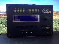
Hey guys! I just finished boxing up my SID and I wanted to share some (fuzzy) pictures of it with you all. I also wanted to thank everyone for all the help and answering my questions. Huge thanks to TK for this awesome project and this awesome community, SmashTv and Wilba for helping to feed the addiction. AWESOME!! The enclosure is made of Birch plywood, and stained blue. Currently I'm running one core with one sid (6581) but as you can see I left some space for buttons and encoders which I will start to add when I get my next batch of parts. I will also be adding more sids as they arrive... ;) Sorry the pictures are blurry, my camera phone is lame. Also, I know the midibox.org sticker is crooked, it was not attached yet. :)
-
Hello TK, Sorry I have not had a chance to reply. Thanks for all the info regarding patch sizes, it's exactly what I needed. I got some 24LC512s from Mouser yesterday and stuffed one into my bankstick. I changed the buffer size in Midi-Ox to 2048, set the delay after F7 to 750ms and it uploaded the patches with no problems. Awesome!!! btw... My 24LC256 behaved like yours did. So patches A002-A064 were uploaded correctly (even though I used Serge's program to upload them). Oh well, now I understand better what was going on. Now to put together an enclosure and wait for the parts for my second Sid module and Step A control surface. Many, many thanks again TK.
-
Hello Thorsten, Well, I finally got a chance to work on this some more and finally achieved success. Sort of... It turns out the soldering, and the wiring was alright. Fot some reason the data was not being written on the the eeprom (I'm using 24LC256) when uploading with midiox. Data was being sent, and I set the 750ms delay after F7 but for whatever reason my banks always showed up as <empty>. Finally I used Serge's SysEx Loader and this worked although not without errors. Maybe Serge's program isn't completely compatible with the latest MIOS or Sid software? Anyway, I have patches now and most of them work. Some do not work at all, neo zelda for example, it is loaded but no sound comes from the Sid (I'm using 6581). I still see the behavior where after patch 64 the lcd shows <no bankstick>. I thought you could fit 128 patches on a bankstick, even a 32k one? I'm going to keep playing with midiox to see if I can figure out what gives. If anyone can point me in the right direction I would appreciate it. Thank you all very much for putting up with my noob questions. You guys ROCK!!!
-
So I finally got a chance to work on this. Changing the device id to the proper one was really simple and now things work more as expected. :) Thanks TK for making it so easy! My bankstick is still not working properly though. I was able to upload the patches but when I try to switch patches, using the keyboard in MIOS Studio, they are not there. The LCD shows <empty>. Also, once I get to about patch 64 the lcd shows <no bankstick>. I wonder if the eeprom was formatted strangely because my core was configured as a slave (device ID != 0x00). I have some new eeproms coming in today from Mouser so I will give things a try using a new chip and see how it goes. Thanks again for all the help.
-
TK....YOU RULE! That must be the problem. When I ordered my pic I got it with a syx device ID of 0x01 not understanding that the device would be seen as a slave because of this. :-[ My bad. I can change this using change_id_v1_9c correct? I will give it try. Thank you so much for the help. This was driving me crazy. :)
-
Alright, maybe I should be more clear as to what my problem is.... So far, I have checked all of my soldering, all of my connections, and traced the wiring of the bankstick. Everything there looks good so far. I even hooked up a scope to the signal lines for the bankstick and sent the vintage_bank.syx file and sure enough, signal. Still however, I cannot access the patches on the bankstick only the internal patch. The setup I'm working on consists of one core, one sid, and an lcd. When I power things up the lcd reads: MIDIbox SID V2.0RC12 CS not enabled! When I plug in the bankstick I get the confirmation "beep" but no sign that we are reading from it. So there must be something I'm missing. Is there a way to read from the bankstick with MIOS Studio? Also, at some point I saw a thread with commands for reformatting the bankstick but I can't seem to find it again. Anyone happen to know how to do this? Thanks everyone for the help.
-
Hello again everybody, I've been beating my head over this one for a few days now and hope you guys can help. I built my bankstick and plugged it into the core module. The core then formats it with, seemingly, no problems. I use midiox to upload v2_vintage_bank.syx with the 750ms delay and that seems to work, at least no errors are reported. Still however, I'm not getting patches. When I plug in the bankstick, I get a "beep" confirming it was plugged in, but the only patch I can play is the default one. I tried using MIOS studio to change patches but that doesn't work either. Is there a step that I am missing? I saw this line in changelog.txt inside of the midibox sid software package: "temporary disabled BankStick routines, so that MBSIDV1 patches won't be overwritten" is this correct or is the document just out of date? Thanks!
-
Quick update..... Looks like my board is fine after all. I'm just a NOOB!!! And had my power plugged into the wrong pins on the core module. This was causing my PIC to only get 3.0 volts instead of 5.0. :-[ Now to install that pull up resistor. Thanks again everyone. One more question....How hot does the SID chip get while in operation? Mine seems to get pretty warm to the touch.