DenDer
-
Posts
303 -
Joined
-
Last visited
Content Type
Profiles
Forums
Blogs
Gallery
Everything posted by DenDer
-
Why don't the pics show anymore? :-\
-
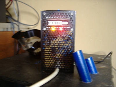
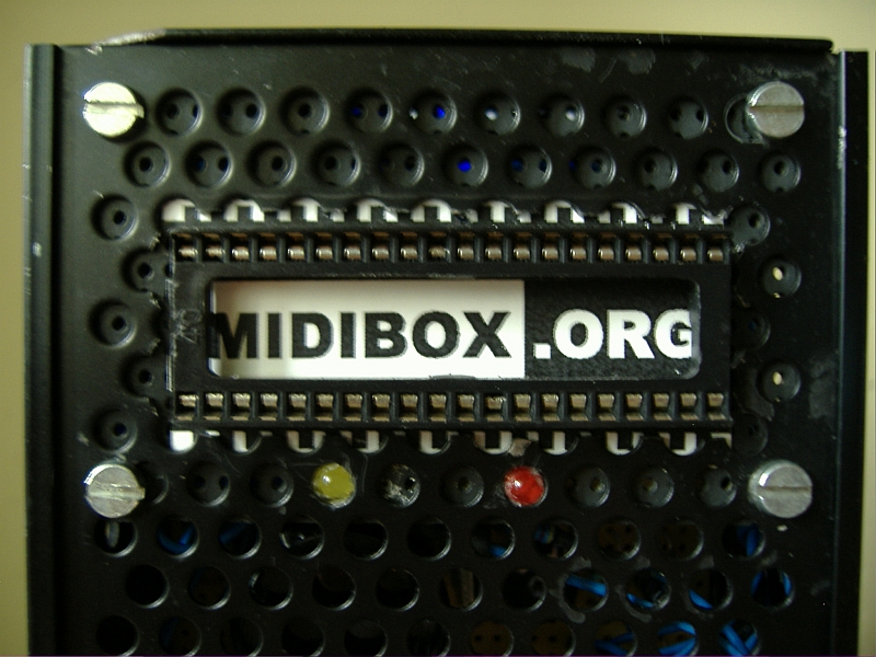
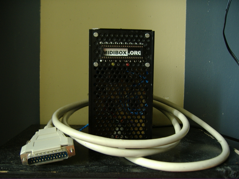
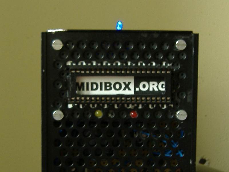
Here are some pics of my Burner build.
-
Building MBHP_ Burner --<<WORKING>>--
DenDer replied to DenDer's topic in MIDIbox Tools & MIOS Studio
And just use the pic18f4685\midi\mios_v1_9f_pic18f4685.hex from the update package.......or isn't this the complete application? ;D And who is Ms. Sophie??? Is she single ??? ??? -
First of all there is a SID_V2_RC25 available........try to upload that hex file of the 6581.
-
Building MBHP_ Burner --<<WORKING>>--
DenDer replied to DenDer's topic in MIDIbox Tools & MIOS Studio
You mean this answer............. o open the Makefile (or make.bat file) and change the ID settings for your needs o build a new .hex file, see also http://www.ucapps.de/howto_tools_gpasm.html (!!! THIS IS AN OBSOLETE PAGE!!!!!) o upload this project like described under: http://www.ucapps.de/mios_bootstrap.html -> the MIOS bootloader will get active for 2 seconds -> thereafter this program will be started -> the MIOS bootloader will be started again, but now with the new ID settings -> the LCD will show the new ID header (if connected) I think i'm getting it. -
Shoeffffffffffffffffff what was that? is it an airplane? is it a bird? no it's the MB forum...shoeffffffffffffffffffffffffffff
-
So this weekend did some additional work on the casing (i weighted the parts that i removed and saved about 750 grams :o ) and a whole lot of reading concerning programming,assembling. :) This is turning out to be a complete DIY project now including programming the pic. If you have a virgin pic, like i did, some questions are bound to be raised. How to convert a .asm file to a .hex file for instance. Well if found out just by reading the dokuwiki windows toolchain at http://www.midibox.org/dokuwiki/windows_toolchain_core Even with my rusty knowledge of DOS ;D it is easy to do. Just follow the steps and you'll be fine. You need to download some progs and install them in an order and you have to change or edit your PATH directory. At first it didn't work for me...to hasty probably.....but now i can convert asm's to hex'xxx Now i can build an application. I'll post some pics of the progress of the casing this week.......it's gonna be o o o so nice. o yeah nice fasssssst forum guys...
-
Man this works like a dream......just followed the directions in the dokuwiki and installed all applications and voila a new hex was born.......when i was a little boy age 10-12 i used to do a lot in DOS..well actually there was no windows.......poking around on a 486, At, XT......making games in gwbasic...what a lonely childhood ;) I guess i'm a geek to.
-
Building MBHP_ Burner --<<WORKING>>--
DenDer replied to DenDer's topic in MIDIbox Tools & MIOS Studio
Okay some questions..... 1. First i burned the bootstraploader in the pic. That is this file : pic18f4685\burner\bootloader_v1_2_pic18f4685.hex I did this for both pics. 2. So now i'm ready to put the pic in the core and upload this .hex file : pic18f4685\midi\mios_v1_9f_pic18f4685.hex But where do you set the ID header then? Or just use the Change_ ID after to make one the slave, since both are burned as the default 0x00??? After i've done this i'm ready to upload the application file of SIDv2....right?? -
:o PIC BURNER is done and working ;D The story on that can be found here: http://www.midibox.org/forum/index.php?topic=11949.msg97825#new The bootstraploader is already succesfully burned so nothing is standing in the way of my QuattroSIDDER V2. Now to upload MIOS and the SIDv2 application and i'm ready to roll....atleast....have a bunch of cables to make for connecting the whole thing together ;)
-
Building MBHP_ Burner --<<WORKING>>--
DenDer replied to DenDer's topic in MIDIbox Tools & MIOS Studio
So today i've succesfully burned the bootstraploader in my 18F4685's. First i did some initial tests with the old 18F452. Succesfully did a hex read out from the 18F452 so the burner is working properly. Sidenote: I'm using the P18 software from www.sprut.de which is a good and easy program but......if you have to burn more than one pic you have to close the program after you succesfully burned one pic. For the next pic, close and reopen P18. Otherwise it won't succesfully burn the next chip. Next step: Installing MIOS thru midi on the core. -
Error in readme.txt MIOS update v1_9f ????
DenDer replied to DenDer's topic in MIDIbox Documentation Project
Yes but take a good look at what is written. First you have to burn the bootstraploader into the pic. So read under burn: Burn: -> pic18f4620\burner\bootloader_v1_2_pic18f4620.hex or -> pic18f4685\midi\mios_v1_9f_pic18f4685.hex the second line concerning the 4685, is actually the second file that you upload after you uploaded the bootloader. And this is done thru midi with the pic in the core. This information may be confusing for some people. -
I don't think this is right....the red part is not right. I think it should be pic18f4685\burner\bootloader_v1_2_pic18f4685.hex From the readme.txt file: E) you want to install the new Bootloader and MIOS release on a PIC18F4620 or PIC18F4685. Burn: -> pic18f4620\burner\bootloader_v1_2_pic18f4620.hex or -> pic18f4685\midi\mios_v1_9f_pic18f4685.hex into the PIC - the directory depends on the PIC type Thereafter upload -> pic18f4620\midi\mios_v1_9f_pic18f4620.hex or -> pic18f4685\midi\mios_v1_9f_pic18f4685.hex via MIDI like described at the http://www.ucapps.de/mios_bootstrap.html page. And are points C and E not the same? Only for different pics.....C for 18F452 and E for 18F4620 / 18F4685...the procedure is the same.
-
Building MBHP_ Burner --<<WORKING>>--
DenDer replied to DenDer's topic in MIDIbox Tools & MIOS Studio
Yes yes y'all its working!!!! So resolved the problem of the missing voltage with some guys in th chat(thnx nILS & Moogah). Had my BC the other way around. Its a bottom view of the pinnig on the burner pdf. But i'm happy now.....my burner is working. ;D -
Building MBHP_ Burner --<<WORKING>>--
DenDer replied to DenDer's topic in MIDIbox Tools & MIOS Studio
Okay the next things occur when the burner is connected to the computer. When i activate Vpp the red lights goes on and off but after a few seconds it lights up again. Even when the burner isn't connected to the comp the red light burns faintly. EDIT: red light problem fixed...forgot to connect both pins(4&5) of IC3 with 1n4148 ::) But still not getting 12,5V at MCLR# pin. -
Building MBHP_ Burner --<<WORKING>>--
DenDer replied to DenDer's topic in MIDIbox Tools & MIOS Studio
Okay guys i need some help. Everything works as it should be but......i'm not getting the same voltage on the MCLR# pin as i adjusted at the TP. At the TP i measure 12.49V and at the MCLR# pin only 8.79V How is that possible? If switched from batteries to a 18V transformer but that shouldn't matter right? -
Building MBHP_ Burner --<<WORKING>>--
DenDer replied to DenDer's topic in MIDIbox Tools & MIOS Studio
So just checked that resisitor but its good in place so something else was(read was) wrong. Recently i've bought BC547's....at least thats what i thought and ordered....but it seems they are BC557's so no good for this project. Swapped it for the right BC547 and everything is working just fine. Vpp test is right, Vdd test is right, clock and data voltages are right, so i have a working MBHP Burner. Now for the next step..... getting new batteries. ;D -
Building MBHP_ Burner --<<WORKING>>--
DenDer replied to DenDer's topic in MIDIbox Tools & MIOS Studio
So just finished up the burner and everything seems fine. :) 1. At start the burner is recognized. :D 2. On the Vdd test the yellow light goes on and the voltages are ok on the pins. ;D 3. Except on the Vpp test the red light goes on but burns faintly and i'm not getting good voltages. Way to low as a matter of fact. So i measured the voltage at the C pin of the BC547 (which i'm using) and its to low to. What is happening here? When Vpp is of i'm still measuring voltage on the line and not 0V. >:( 4. Clock and data behave normal. :P Okay just checked the board and one resistor isn't placed right.......gonna change that and report again later. But there is life in my burner. Anybody any answers? -
Building MBHP_ Burner --<<WORKING>>--
DenDer replied to DenDer's topic in MIDIbox Tools & MIOS Studio
Phiiiiiieeuuuuw(wiping forehead) then i'm building the right things :o at least ::).........yeah i think so ??? But i thought i was building a microwave........to cook up some basslines ;) -
Building MBHP_ Burner --<<WORKING>>--
DenDer replied to DenDer's topic in MIDIbox Tools & MIOS Studio
Don't know actually...MBPH ??? ??? Maybe a new degree of studies ??? ??? MBPHd(ender) ;D -
Building MBHP_ Burner --<<WORKING>>--
DenDer replied to DenDer's topic in MIDIbox Tools & MIOS Studio
I thought it had something to do with the amperage. At least that's what they told me. Like 4002 is 2A and 4007 is 7A. edit: you're right again with the voltages. But isn't it the same as with elco's? You can use a 400V cap for a 12V application, everything above the appropiate voltage isn't needed. Don't know if the same counts for diodes though. -
Building MBHP_ Burner --<<WORKING>>--
DenDer replied to DenDer's topic in MIDIbox Tools & MIOS Studio
Just swapped the LM317 and ihaaaa 12V (one 9V battery is low) :o So good voltages now 8)....Thnx DrBoom you're right ;)......got the LM the other way around so this solved my problem to.........it's not quite finished my pic burner but good voltages are always nice. -
Building MBHP_ Burner --<<WORKING>>--
DenDer replied to DenDer's topic in MIDIbox Tools & MIOS Studio
Okay good you mentioned the regulator. Did some background work and came to the conclusion that a 'normal' LM317, which i'm using, has a different pinout then the LZ version. Correct me if i'm wrong....... But i might think that you're right. Gonna turn it around and get back to ya'll..... -
Building MBHP_ Burner --<<WORKING>>--
DenDer replied to DenDer's topic in MIDIbox Tools & MIOS Studio
Well just glued the components to the exp.board and the green light lights up ;D but........i'm not getting anything near 12,5V......at the lowest point its about 0,60V and at the highest about 5,7V... :-\ that's not good..... So i'm wondering...instead of a 1N4002 i used a 1N4007....does that matter? And the trimpot is a 2k5 but i ordered 2k2...does that matter? On the 5V line i measure only 4,25V. What am i doing wrong here??? But at least the green light lit up ;D ;D ;D -
9 augustus "Underbase"@ Militär Basis Heitzerend,Grefrath
DenDer replied to DenDer's topic in Miscellaneous
Je ne sais pas bon ami....... :P I also spray grafitti and DenDer is also my tag ;D