DenDer
-
Posts
303 -
Joined
-
Last visited
Content Type
Profiles
Forums
Blogs
Gallery
Everything posted by DenDer
-
Building MBHP_ Burner --<<WORKING>>--
DenDer replied to DenDer's topic in MIDIbox Tools & MIOS Studio
Okay thats clear...thnx nILS :D I'll report again after testing........i love these puzzles. -
Building MBHP_ Burner --<<WORKING>>--
DenDer replied to DenDer's topic in MIDIbox Tools & MIOS Studio
Okay just downloaded the pdf for the trimpot(piher pt10) and the markings are as followed: solo pin is the wiper(S*), the two other pins are marked initial(A*) and final(E*). http://www.piher-nacesa.com/pdf/12-PT10v03.pdf So the wiper(S*) is connected to R1(220 ohm) and the final(E*) to IC1:A. The initial(A*) goes to ground. Is this about right? -
Hi, At the moment i'm constructing the mbhp pic burner on a piece of exp.board. I've got a question regarding the trimpot. How does this go on the board? When i look at the schedule pdf you've got the 3 pins of the LM317, I*,A*,O*. The trimpot should go between A* and O* but how? There are 3 legs on the trimpot, two on one side and one is solo. I'm figuring that one of the two should come from O* (with a 220 ohm R in between) and the solo one should go to A* and the negative line. The third leg goes to ground. In the pdf it seems that the resisting value of the trimpot is between O* and the negative line. But do i have to connect that leg also to ground after J2? Trimpot.JPG
-
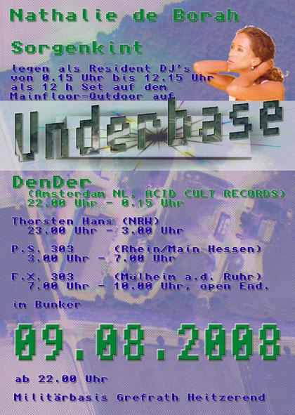
Hi, this saturday i'm playing at Underbase....... Line up: SORGENKINT NATALIE DE BORAH DENDER Starts at 22.00 till open end.......so for all you germans come and check it out. ps. non germans are also welcome ;D
-
Damn what's that smell ??? ??? o it must be your ego ;D
-
But your name is 80.. ;D what's with that then hu???? 8) 90 secs come you can do better than that laddy!!!whahahahaa ;D nice going.
-
So today my 2 pic's 18F4685 arrived .....totally virgin chips.....so i'm going to build a pic burner as described on uCapps. The parts that i ordered are in the mail and i hope they will be arriving tomorrow. Also a lot of other parts for the build are in that order.....like mounting stuff for the pcb's. Think about that, i forgot actually. :-X I'm going to stack 2 SID boards on one another (2x), stack the three DIN boards and the 2 DOUT boards.....the 2 core boards will be placed next to each other.... For mounting everything inside i needed 36 times m3x8mm for the underside of the pcb stacks and 76 times m3x18mm mounting spacers.....the additional nuts and bolts where already in tha housah..... Some questions regarding the audio output........ As you know i'll be using 4 SID chips >:( :P So that leaves some options..... 1. 2x 6581 and 2x 8580 2. 4x 6581 3. 4x 8580 I have enough SID's lying around but haven't tested them all as of yet. If i would go for option 1 i have the old chip and the new chip in 1 box with 2 stereo outs but is it then also possible to have one master out with all 4 SID's combined? So 2 stereo outs per chip + 1 master. Or is there then an alternative circuit necassery to amp this? Could this be done with JRC 4558 opamps? The nicest thing i can think of is 4 mono outs per SID, 2x stereo out L/R and one master.
-
Opto's, DenDer frowns and strikes his beard........hmmm isn't it the other way around??? Right stryd? ;D Check the opto...
-
cs not enabled sid stereo 6582 simple surface(one core)
DenDer replied to boops's topic in Testing/Troubleshooting
Hmm i'm having the same problem as Boops......also cs not enabled......but to quote TK "cs not enabled" means "Control Surface not enabled". It seems that you've uploaded the .hex file for a slave module, or you've selected the auto CS feature, and the device ID of the core is != 00 Best Regards, Thorsten. Now i want to know the 'or' part......how do you disable the auto cs function? I'm pretty sure that my core id is 00 since it is the master and i still get cs not enabled. -
Pic 3,4 and pic 5 shows the 8x8 led matrix 8) 2008_0731Image0031.JPG 2008_0731Image0032.JPG 2008_0731Image0034.JPG
-
As promised some pics of the progress on SIDDER. The first pic shows the panel as it was and as it is......i cut away all the sides to make a smaller box. Dimensions are around 25 by 19 by 8 cm :o. I think this is going to be the smallest full surface MB SID build... :D The second pic shows the under frontplate...notice how nice the rotary encoders fit in the existing holes :) look like its made for it!!! The third and fourth pic shows what the box is going to look like in the future.....already snucked in the lcd. At the left you can see the original hole for the mixers VU meter and a hole for the mixers mic input(xlr). This is going to be removed to. At the right you see two big holes what ones was a punch in function on the mixer......that side is going to be removed to. At the right upper corner are the 1-5 select buttons and the sid selection buttons. The open hole over there is going to be used for the potmeter of the feedback loop modification. 2008_0731Image0028.JPG 2008_0731Image0029.JPG
-
So just put myself on the list........this is a nice addition to my SIDDER. ;D Thnx Seppo!
-
Hey Jim just sign yourself in on that page. Then the edit button is where it should be. Then you can put yourself on the list.
-
Dude just read the schematic......optimized psu 8xsid.....AND NO VOLTAGE REGULATOR ON THE CORE!!!! Only on the OPSU and SID boards.
-
This stuff is what keeps me going when the shit hits the fan.....put aside your project for a moment and listen to what you're working for. Yeah i like the sound even better know..especially in the beginning....on only the first 10 seconds you can build a song.....nice going TK.
-
I actually like the white panel around the lcd man! Some contrast on your MB sid......very nice,yet again.
-
That's absolutly true 8) but i have to check if they will fit in the enclosure......i mean 2 core's, 4 sid's, 3 din's, 2 dout's, psu and banksticks + lcd its gonna be a close one... Just made a mock up of the ledmatrix and that looks nice.....now only have to figure out a new layout for SIDDER...i want to use some of the layout of the mixer (knob spacing is nice) because it uses a double surface. I can connect(screw) the rotary encoders directly to the under surface and the top surface will hide the screws.... You know what i'll take some pics tomorrow ;D
-
Nice going dude ;D Can you put in some smaller pics? Can't see the whole thing in one frame.
-
Another question...when you connect 2 core's, only the master core handles the midi in and out right? And leave out the optocoupler of the slave core. Yet another question concerning the connections between the DIN boards. If i look at the double J1 header and the double J2 header i don't understand how to connect S0 and SI. Goes S0 to S0 or to SI from J1 to J2? And o yeah, i've made an executive descision about the housing of my SIDDER.......i'm going to build it inside an old mixer which belonged to a friend of mine. It was beyond repair.... (people should know now that mixers don't drink alcohol, although their name would suggest otherwise ;D )
-
Assuming you are using a SID V2, since you want to connect 2 sid's to 1 core, did you check the connections between the core and the 2 sid's? They are not exactly the same as you can see in the optimized psu 8xsid. You don't have to connect S0 J2 between the 2 sid's. For the second sid you have to connect core J14 to S0 J2.
-
So it's been 2 months now since i've done anything on my working SIDDER....... :-[ I've have ordered 2x 18F4685 Microchips.......so i'm upgrading to MB SID V2..... :o All the parts are in the house now including exp.board to hook up all the tact.switches en rot.encoders. Also did some work on the case for which i had to make a bottom board to keep the 4 datasettes enclosures together. At the moment i'm finishing up on the soldering of the remaining SID boards and the second core is going to be soldered tonight. Some questions: With the second core i don't need the midi connectors...can i just leave them out? For the third DIN board can i leave out the 3 unused ic's? But put in the 10k pull ups..
-
SID 6581 & SID 8580 in the same Midibox SID V2...Possible?
DenDer replied to SaMSeMiLia's topic in MIDIbox SID
But can you control 1x 6581 and 1x 8580 from 1 core? If yes, which hex file do you have to upload to the core then? The one for the 6581 or the one for the 8580? Not that i'm going to do this but just wondering. ;) -
Never had any problems with them. They are the cheapest and have a wide range of pics etc. So i'm suprised to read all this negative info about them.
-
Schön,schön.......looks nice dude!!!
-
That's true.......i'm wondering where all those wires are for that he has connected.