

strophlex
-
Posts
536 -
Joined
-
Last visited
Content Type
Profiles
Forums
Blogs
Gallery
Everything posted by strophlex
-
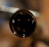
As you see both middle ones are connected together and I guess they are pin 4&5 of the connector, so they are both 5V pins. The Outer top ones are not connected and the top middle one must be ground.
-
Strange, but it explains it.
-
This is a picture of my PSU connector. It has the four interesting pins only. The numbers are relative to your picture and might be mirrored compared to the image at allpinouts.com. If you compare it with your connector, you should be able to figure out if it is the right pin that measures 5V. It is the one labeled 4 in the photo. Good luck!
-
It must me easy to confuse left and right side at some stage. Maybe pin 4 in the picture is actually the 5V pin. Looking at the power connector and observing the pin you have measured to be 5V. Does that pin mate with the pin labled 4 or the pin labled 5 of the socket in the photo? It makes sense that pin 4 (on the right side of the socket) mates with the trace to the right in the image (which is connected to 5V as you see in the photo) Reference. http://www.singatron.com/eng_pdf/2DJ-0077PA03.pdf It is probobly not the same connector, but it has the same pinout and so is proboly more or less identical.
-
It sounds like you might have found a problem then. - Disconnect the powersupply and make a continuety check between the inner pads on the board (5V and gnd) - Double check that the 5V on the PSU did not brake (blown fuse) - try to continuety check from 5V in of female connector (pin 5) on the board to the pad it is soldered to to make sure the din connector is not broken. - Do the same with the gnd (pin 2).
-
Did you measure the switch or the female power connector on the board?
-
Double check that no resistor network is flipped around. I got a similar problem when mounting every second resistor network in the opoisite direction.
-
Suscribing since June 20th 2011 for a Wilba's PCB
strophlex replied to Philippe Nocq's topic in MIDIbox SEQ
I don't know any details, but I say have patience and don't worry. Often these thing take time. I've been waiting for Doug Wellingtons MB808 pcb since january 2009... EDIT: Allso, take a look at this thread: -
Think of your wall outlet. It doesn't have a + and a gnd connector but two ac connectors plus possibly a ground connector. There are two AC connectors that alternatively push and pull electrons. When you measure one of the AC pins against ground you are measuring a voltage that is fluctuating between 0 and 9 volts. That is not really what you measure if you measure the two ac pins. As I said, don't confuse ac and dc.
-
Don't confuse the DC and AC pins. Pin 5-2 should measure 5V DC Pin 6-7 should measure 9V AC Don't mix and match. Measuing between dc and ac pins will give you strange readings.
-
You should locate if and where there is an unintended bridge between ground and +5V. First mesure with continuety mode and if no short is found, connect psu and make sure you mesure 5V between gnd and +5V. Now that the bridge is removed, you can apply some divide and conquer methodology. If the first part of the PSU looks OK, resolder the power switch. Think twice before doing. It will help you if you make notes as you go along and make messurements. Good luck!
-
Where can I find latest MIDIbox SID Synth firmware?
strophlex replied to brokenchip's topic in MIDIbox SID
http://ucapps.de/mios/midibox_sid_v2_040.zip -
Good luck and keep the faith. Your synth will be operational soon.
-
-
mios and bootloader is not the same thing. first you burn the bootloader to the pic and then you upload mios via midi. the bootloader is tiny. mios is the os. http://www.ucapps.de/mios_bootstrap_newbies.html
-
Use MIOS studio to send the hex via midi. I am pretty sure you don't need to burn the PIC. The bootloader doesn't have to be changed.
-
Your PSU brick is not the same design as mine, and mine doesn't have an external fuse, so I am not sure your has an internal one but anyway it may be that the external fuse is blown. Check it with your multimeter. It might be broken although it looks OK to the eye.
-
I don't understand what you mean with the fuse outside, but yes, there is a fuse inside. It is easy to replace it and fuses are cheap but leave the brick disconnected from the wall for some hours before opening it and be careful when replacing the fuse. Also, I don't understand what you mean by square connector.
-
Messure the 5V of your PSU again. I suspect the fuse in the PSU to be blown but the reason for that is probobly a short on the board somewhere. If the PSU is still OK, it is wrong that you have no voltage at the connector. Try to verify that the pinout of the PSU is right... Concentrate on mesuring dc voltage with the power switch off to verify the first few parts of the power supply section of the board.
-
You should not measure current. Do it again and messure DC voltage. Also, be very careful when dealing with the probes when power is on. It is easy to break the fuse in the C64 PSU.
-
If these readings are correct it seems there is a short between the switch and J73 somewhere. As SmashTV said, it might be that the capacitor is acting like a short to the multimeter. Next thing to try would be to connect the PSU and measure DC at the power connector pins (2 and 3) with the power switch turned off to make there is no short before the power switch in the ciquit. Do you get my resoning?
-
Make a continuety check between pin 2 (5V) and pin 3 (GND) of the power connector socket with PSU unplugged. Try this with power switch both on and off. Look at the schematic to find these pads. THey must be checked from under side because the connector is in the way from above.
-
So, the state now is that - the bridge at J73 is removed. - The power switch is soldered. - There is no short between ground and 5V. (Measured by connecting multimeter in continuety mode between J73:pin2 and J3:GND for example. PSU disconnected, power switch on and no beep from meter). - There is 0 V DC reading on multimeter with PSU connected and switch on between J73:pin2 and J3:GND. Did I get all that right?
-
Too bad. Then I have no idea. Is it allways in steps of 10? Is it the same in settings menues?
-
THe firmware for the MB6582 and SammischSID is not identical. Try uploading the hex-file built for the Sammisch...
