

latigid on
-
Posts
2,524 -
Joined
-
Last visited
-
Days Won
149
Content Type
Profiles
Forums
Blogs
Gallery
Posts posted by latigid on
-
-
I agree with Zam: probably those DAC channels are dead (but do check directly at the pins). The TLV chip is quite sensitive to heat.
-
12 hours ago, Menzman said:
Hi everyone,
just finished my first V4+!
-->Big thanks to Peter and Andy for their great work (and support) to make this machine happen!
After playing around for some hours I found out one issue with my build: Always the eights encoder (8 & 16) do not react as expected. The encoders are jumping in the wrong direction and also opening random-like pages/functions when using them. :-(
Great work and nice pictures!
Are the encoder pins in question shorting out on the pinheaders below? If so, trim the pins a little.
9 hours ago, gbrandt said:Hi Peter,
I'm happy I can contribute a little bit back after lurking all those years :-)
Concerning the LED, i've marked it in red now which means parts where people should be careful in replacing.
And I checked my previously bought MIDI ports again from both Tayda and Mouser and it's true Tayda seems much cheaper and doesn't have a nice metal casing. I marked those, too.
Another thing I noticed, not related to Tayda, is that the MEC switches are out of stock at Mouser now. too many SEQ V4+ builders? :-)
I did find some at RS so might order from there (unless someone has a huge stock and wants to make a nice offer),
but i'll eventually add more columns for other vendorsCheers,
Gerhard
I'd recommend Reichelt for MEC switches. Conrad also sells them, and the caps I think are cheaper there.
-
 On 1/4/2019 at 11:34 PM, latigid on said:
Ah right, these can be very confusing! Also, the way CMOS labels power connections as Vcc Vdd Vss etc. can also lead to mistakes.
I didn't check the pin compatibility (please check!), but this PCB might help:
-
I've done exactly this (with the board outline at the edge) at OSHPark. About half of my boards had missing copper though, as I suppose the router can pull the plating off.
-
Maybe you can get it to a single layer by routing through the SIP header.
For pads to the edge, you could consider a castellated pad/via. Normally the fab will charge extra for it. I'm not sure if it's a good idea mechanically; the simple pin header would be stronger. Or maybe I don't understand your idea.
-
Drum labels sound like an extremely useful improvement!
-
When you look at a male IDC pinheader from the top, the pins are numbered
 ________________________
|02 04 06 08 10 12 14 16 |
|01 03 05 07 09 11 13 15 |
__________----___________
Because we normally connect displays on the rear side, the Core J15 is mirrored, so it's actually
 ________________________
|16 14 12 10 08 06 04 02 |
|15 13 11 09 07 05 03 01 |
__________----___________
Thus the pin numbering starts at 01 in the bottom right corner.
Could you check that these pin numbers correspond to those on the LCD when the cable is connected (with the power off)? Or are the pairs inverted as Bruno says?
Otherwise the pinning on the LCD (unless it's mislabeled) looks to correspond to the Hitachi standard.
-
Ah right, these can be very confusing! Also, the way CMOS labels power connections as Vcc Vdd Vss etc. can also lead to mistakes.
I didn't check the pin compatibility (please check!), but this PCB might help:
-
Did you connect the IDC16 cable on the top or the bottom of the display?
-
Awesome! I keep noticing the blue/green flashes underneath the USB cable :)
-
10 hours ago, Antichambre said:
Andy,
For future case production, you can maybe open the metallic plates between the two left mounting hole and use this type of header:
Just an idea, cheers!
BrunoA good idea and one I had considered, but I think the cutout would weaken the plate too much there. Plus, the clearance to the I2C board will be quite close when the case is in rack mode.
I had a look at headers mounted to a tiny PCB, but I think there's just not enough room, even with micromatch or "paddleboard" type. Consider 10mm spacing, 2.54mm plastic standoff on a straight-pin header, then a 1.6mm carrier PCB. I didn't find a header lower than that height difference. I would suggest to put a sliver of kapton tape on the components/IDC.
-

If you wish, it is possible to bridge the pairs of pins 4/4 and 5/5 as shown (viewed from the top of the board). It isn't done by default, as simultaneous use with a BLM would cause a conflict and perhaps an expectation of an "extra" MIDI port. If you and any future owner of the SEQ are aware of this it should be okay.
-
Great that you found the solution!
The mounting is very tight indeed, and insulation seems like a very good idea.
I wonder if it's better to rather mount the IDC directly to the OLED, for instance using:
HIF2E-14D-2.54RB(20)
(only 14 pins, but it would work, as the backlight is not required. HIF2E-16D-2.54RB(20) is not in stock at Mouser, but could be ordered. There's also the RA type (grey colour I think)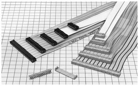
-
Have fun! Keen to see a video of the jam/performance (if available) :). Are you using the Host port (USBA) of the v4+?
Lots of people are asking for CV/gates for SEQ v4+, so I will work on a DIY solution using the intended Line Driver. I think I have a way of generating the +5V inside the Eurorack case that should avoid sending power down the DB-25. Will need to be tested of course!
Not intended to discount the FH-1 solution in any way! It's great if it works for you.
-
Great job! This is with the 62083 chip to drive the activity matrix, correct?
I have almost everything ready, but I've been doing PCB design/mods the last days... I'm happy to be beaten to the finish!
-
3 hours ago, rbv2 said:
those switch-caps and led-window looking great. also the color scheme is fresh.
after the completion i realized how important it is to have the super flux leds exactly in the middle to achieve an even illumination. seems obvious, but i didn't think about it.
Consider giving the leds another try. ...still have six left :)
is there a special reason for the size of the cutouts for the super flux leds?
maybe a good idea to make the cutouts a bit smaller in a future revision of the le mec pcbs?
greetings
rbv2
...
I would like to add that this is a very pedantic observation :P
I will request that the fab cuts the next lot a bit smaller. We're at the lower limit of the corner radius for the router bit though, so there's not much to be gained. If you centre the superflux legs on the SMT pads, you can control the diagonal displacement to get it a bit more in the middle. Personally, I never noticed an issue with alignment, even with the LED at the side of the cutout.
It is actually possible to increase the light transmission by wrapping the sides of the Matias switch with alu foil. Although the risk is low, I wouldn't recommend, just in case the foil falls off and shorts a component. Maybe there's some sort of foil tape?
-
Nice machine Bruno! Great mods!
-
Ace! Very nice job!
-
Just what I would've suggested. Great that it's going now!
Best,
Andy-
 1
1
-
-
Merry Xmas!
62083 is available at TME:
https://www.tme.eu/at/details/tbd62083afwg/treiber-integrierte-schaltungen/toshiba/
Best,
AndyP.S. fantastic work so far!
-
-
Is there something like an "enter" button? Seems it would be useful e.g. to confirm a "flashing" menu item when using the jog encoder push function.
-
For best brightness balance (and LED lifetime), use the latest specified values. The others will work though. You could also get creative with adding two 22R together if you happen to have spares.
What is your colour scheme? Normal red-green or something else? Note that the firmware will allow to swap LED colours around. Obviously this only works with the connected LEDs. Peter did a "cyan-red" version for his first build. You can do this by doubling up green and blue for example and use the extra pad located on the RJ.
-
FWIW, I would still suggest to order the Beat LED with the main order. You normally won't have to pay for shipping a second time on backordered parts (at least I've received a smaller packet later in the past).

midiphy SEQ v4+
in MIDIbox SEQ
Posted
Pictures? You can also use the dedicated thread here:
The random data might indicate floating 165 inputs.
Other ideas:
BLM positions are here. SR side is as you would expect, but also attached here for convenience.
Best from snowy Boston,
Andy