

latigid on
-
Posts
2,524 -
Joined
-
Last visited
-
Days Won
149
Content Type
Profiles
Forums
Blogs
Gallery
Posts posted by latigid on
-
-
Aren't the GPIOs used as LED outputs already at 3v3? So where are the current values derived from? E.g. the Res/SD board specifies 1k for each in the BOM tool.
? don't really like giving resistor values for LED brightness, as it's always so subjective. Starting values, sure, but you can always season to taste.
-
Just now, rbv2 said:
right.. twelve was said in the video.
Again, I'm not sure where? Twelve ports maybe? Anyway, no bother
 .
Just now, rbv2 said:
.
Just now, rbv2 said:it's certainly a bit exaggerated with the 16 ports but i'm using expert sleepers at the moment with 16 midi out and thought of a simple switch box that allows me to determine for each synth whether it gets its signals from the computer or the hardware sequencer without moving a cable.
guess eight outputs will be enough anyway :P
The SEQ v4(+) natively has four USB busses, each with the normal 16 channels. IIRC the USB-MIDI communication protocol is even enhanced over DIN-MIDI. So if your interest is interfacing with softsynths and hardware, that comes right out of the box!
Of course for the synth dungeons, something like Bruno's moar16 would come in handy, but the "basic" SEQ can already do quite a lot.
-
Thanks for the kind feedback!
I'm not sure where you got 16 MIDI outs from? The max here would be 8 (MIDI8 + I2C). There is a possibility to use a second I2C with a firmware hack to gain 4 more, but for space and latency versions this wasn't included in the standard build. @Antichambre is developing a 16x16 MIDI expander but again it doesn't fit in here. Another thing I can think of is hosting a GM5x5x5 or the newer chip, but it's also not in the plan nor complete at the moment.
Of course you have 8 outputs with 16 channels each, so plenty to work with using the 16 sequencer tracks. What was your plan with 16 MIDI outs?
CV/gate would go through the DB-25 line driver. On the other end AOUT/DOUT modules are required (under development, some solutions already available).
-
I haven't tested the 5E, indeed it might be too short. The LED mounting is also different and has no "groove" to fit inside. But hey, feel free to try if you like the aesthetics better.
-
Sure, might even be better. I left the panel spacing up to Adrian and have never seen the case in person yet :)
Not sure if 5G fits? Butthere's 16mm:https://www.mouser.com/ProductDetail/MEC-Switches/1S11-160?qs=XkGcM6gst%2F8pgAO1bVm7xw%3D%3D
-
Just now, Antichambre said:
I like this blue too... Is it the picture? If it's not a the picture and not a color accident in the dosage I'm interested in this color code.
Would need to talk to Adrian about different colours. It might be that the cases are ordered in low (e.g. <10) quantity, which could leave some room for customisation. Very likely we'll keep a stock of "standard" colours though. It's too much to keep too many options, especially considering we start with two possible variants (LH/RH).
Just now, Antichambre said:Finally what is the best height for the Apem? How much is a 15mm button flush at rest?
I'll leave you to check the datasheets if you're interested. The switches have 1mm travel. 19.0mm caps are suggested.
https://www.apem.com/int/multimec-3f-287.html
http://www.produktinfo.conrad.com/datenblaetter/700000-724999/705191-da-01-en-MULTIMEC_KAPPE.pdf -
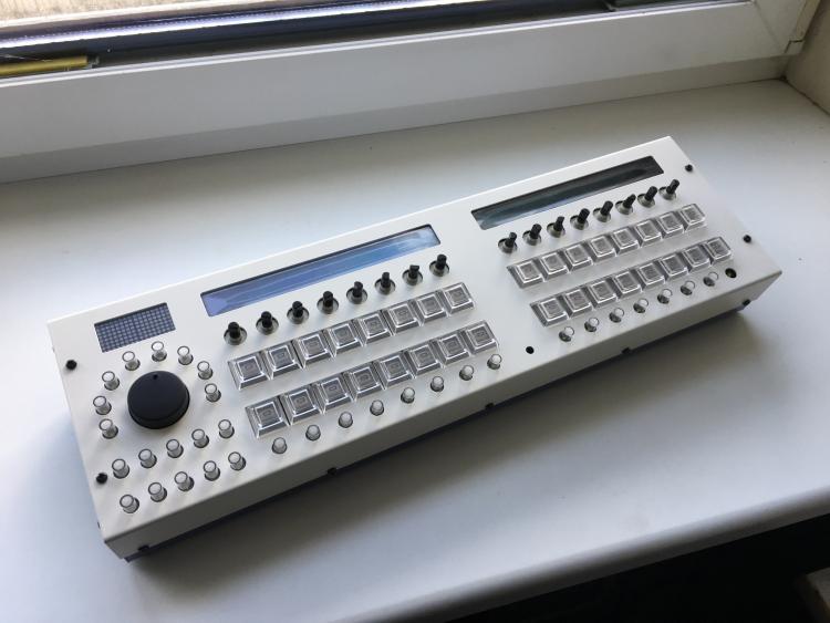

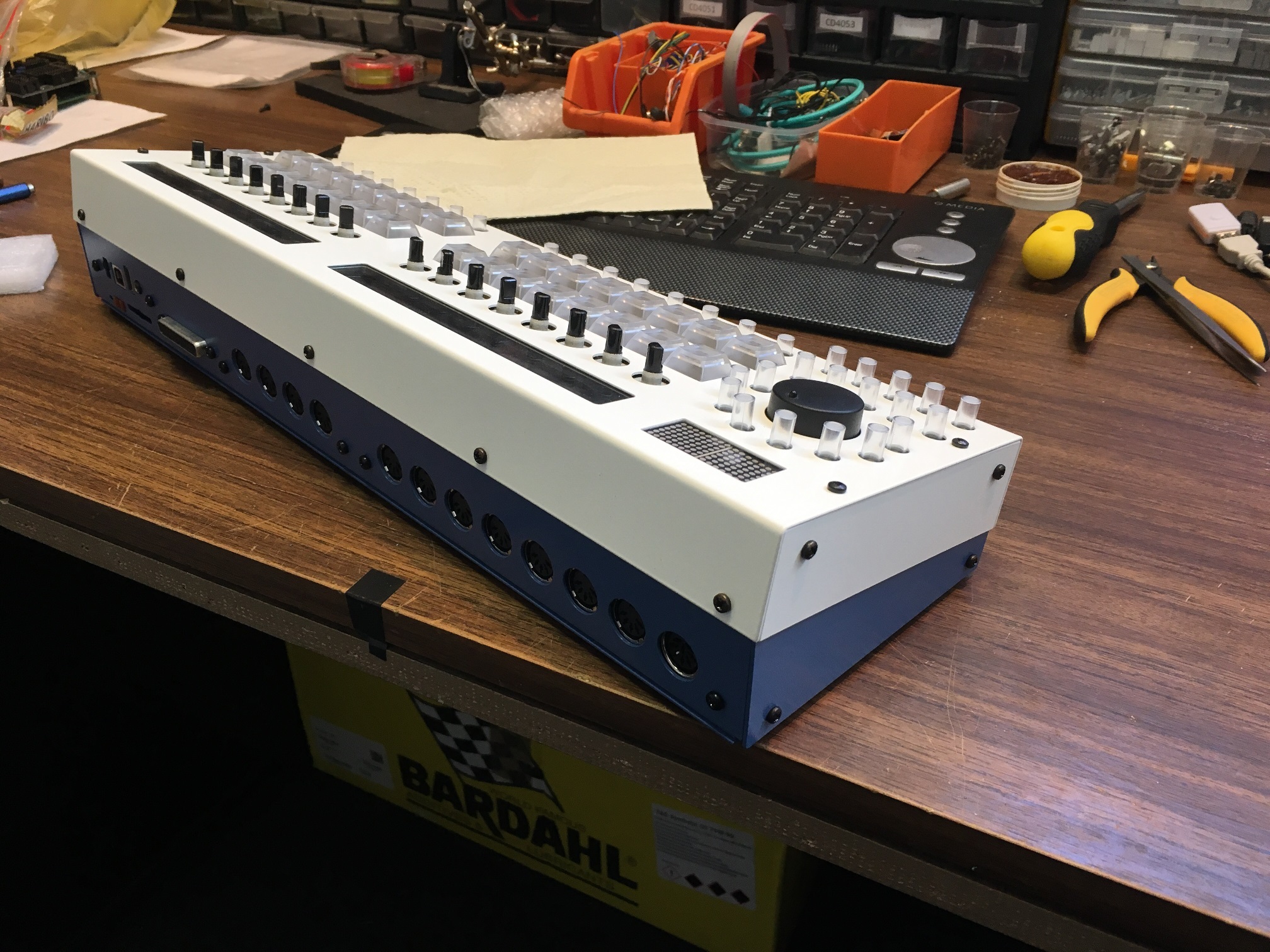
Lefty version from Adrian. The Apem caps on the JA board are too tall, they should all be the same height. The blue will be lighter in real life.
-
It's one of those things where you just try and see how it goes. There are other tricks too, such as RC termination or buffering. All need extra circuitry, so give it a go first.
-
 1
1
-
-
It's not a priority at the moment, sorry.
-
For some reason I thought you only had an LED matrix. So you actually need:
- +5V
- 0V (ground)
- SO (serial out)
- SI (serial in)
- SC (serial clock)
- RC1 (latch for DOUT)
- RC2 (latch for DIN)
You could probably get away with sharing RC1 and RC2, but still that's more pins than a DIN5 has. Or did you power it somehow differently?
-
1
-
Did you consider using the DIN8? Or do you plan to build a 16x16+X BLM?
-
1
-
-
The three pins were intended to connect a MIDI port if the BLM wasn't used, hence using the standard MIDI pins and leaving the others floating. This was before the days of MIDIO/MIDI8. So it should work to connect, but yull deffo need some bodge wirez maaate!
Keep in mind that the SRIO signal can get dicey if the cables are long. This would be the idea of the Line Drivers.
-
1
-
-
With regards to naming, I don't want to take the v4+ moniker away from Wilba ones. Although it's true that the version I've designed (with input from Adrian/TK./Peter/Bruno) does represent UI improvements and thus fits with the "plus" suffix as put forward by TK., any F4 Core version will run the V4+ firmware.
TK. created the hardware config "antilog," which is the name I use for PCB projects. You could also call it the latigid version, the andy version, whatever :).
-
45 minutes ago, ilmenator said:
Peter, nice work! Also good to see a mini-TPD,
To differentiate from Peter's TPD (or your PCBs), the one built into the SEQ is called the "activity" matrix. This means we have a JA board (jog wheel + activity). When he has time, Peter intends to add some extra features to display. Not sure if they'll necessarily be compatible with the TPD.
45 minutes ago, ilmenator said:albeit this seems to have only a single color?
Well spotted! The colour choices on the smaller ones are quite limited, although it goes with the "clean" look of the UI.
45 minutes ago, ilmenator said:Are the UI schematics publicly available or do we need to reverse-engineer them based on the v4+ config file?
I'll probably put the matrix schem up at some point. For now, I'm happy to supply it to those who have purchased the PCBs (just Peter, Adrian H, TK. and lazy beta testers :P ) or to those who need troubleshooting advice.
-
Ah, you want clock input. Not currently supported in the SEQ I think, but I believe it was done in the CV app? You can ask in the general firmware updates thread.
-
2 hours ago, gohan2a said:
- JCI port not used here (it's planned to use these lines for DIN Sync Clock and Start/Stop input in future)
Correct. Clocks and start/stop (i.e. "DIN sync") are sent over the DOUT shift registers. JCI is not used.
Check in the CV config:
Quote- Clk: selects 1 of 8 clock outputs (available at a dedicated DOUT shift registered which has been configured with the CLK_SR parameter in the MBSEQ_HW.V4 file). Each clock has an individual clock divider, or can optionally be used to output a Start/Stop signal
-
I don't understand the question sorry. Gates and clocks go through the DOUT (SRIO) chain.
-
9 hours ago, Phatline said:
good input, will integrate that!
If you use a non-standard protocol, consider using a different connector e.g. a DIN5 240/270 degree pin pattern.
-
I would say it's about 50:50 SMT/THT. I also don't like squinting too much, and that's why the resistor/cap packages are 1206, the transistors and diodes SOT-23 and the chips SOIC or larger. This can be easily done without a microscope. I recommend to use a decent light source and check the joints after.
People who've never done SMT before are often surprised by how much quicker it can be than through hole. No lead forming, no flipping the board (if you bottom solder), no parts sliding away and no lead clipping. Tack one pad, align the part, finish the other pads. Use a low angle with the iron and heat the pad rather than the pin. Even use a solder sucker to remove excess solder.
-
At the moment that's the idea, yes. What customisation did you have in mind?
-
1 hour ago, encoder said:
Do I really need the LCD?
Recommended at least for building/debugging.
1 hour ago, encoder said:- yes, that DB plug looks fun, but originally, I wanted to keep the bankstick inside the enclosure, do not want to swap them
No worries, just solder onto a piece of perfboard etc.
-
Hello, welcome to the forum. I'll try to answer your questions.
13 hours ago, encoder said:- I'd like to build the total minimum version, because I can create a handsome little M4L editor to it an with this, I can store the presets with the Live projects. For this little setup, If I understood correctly, I need only the core PCB, the SID PCB, a power supply, maybe a bank stick and the SID, am I right?
Check out the "Step A" build. This is the minimum control surface http://www.ucapps.de/midibox_sid_cs.html
13 hours ago, encoder said:- Is it possible to solder create a small PCB, instead of using the BankStick? Is it easy to re-write the presets? 127 patches are far more that enough for me.
You can even use a DB plug for a bankstick:
http://www.ucapps.de/mbhp_bankstick.html
13 hours ago, encoder said:- I have a PICkit 3 programmer, can I use this to program the PIC?
Cross-reference the list of compatible devices with the PICs you intend to use. Note that only the initial bootloader flash is done with a programmer, thereafter over MIDI/MIOS Studio.
13 hours ago, encoder said:- About the power supply, let's say, a 12V DC PSU, 1000mAh is enough to power both boards?
For two SIDs only? Probably okay.
13 hours ago, encoder said:- I'm a bit confused about the engines thing. So, can I use the module without the controls? I mean, can you access all of the parameters VIA CC or SySex?
Step A CS should work.
-
1 hour ago, Antichambre said:
It seems you put CV/Gate Outputs :) Great!
Add it in the Main features list, this is an important point.
Actually only inputs are supported, you'll need a converter to use CV/gate. In principle it could be done as all expansion headers are there. I don't think the software handles CV and there is not much push from our side to squeeze it into the current box. A bigger unit might work.
On that point, this represents another Core with DIN MIDI onboard. We could consider other "stackable" add-ons for small synths or controllers.
-
Generally try to provide as much info as possible here. This way the people trying to help you don't have to go looking though everything. The multiple info on this pedal or that and how these people do it isn't helping me help you.
You have the schematic on how a MIDI in will work, you need to find out what your pedal does and how it supplies the +5V. Otherwise you need another power adapter to do so. My guess is that it happens with the ring terminal. Two options were provided to you to arrange the optocoupler on a known PCB design or a piece of perfboard/protoboard.

Midi Out not driving X0XB0X Midi In
in MIDIbox SEQ
Posted
MIDI is actually a current loop, not really anything to do with voltages.