

latigid on
-
Posts
2,516 -
Joined
-
Last visited
-
Days Won
147
Content Type
Profiles
Forums
Blogs
Gallery
Posts posted by latigid on
-
-
Have you tried restarting MIOS Studio between updates?
Jumper settings appear correct.
You can also measure resistance between the USB B port (with power off) and PA11/PA12 on the socketed Waveshare MCU breakout, should be 22R.
-
Thanks for the nice feedback! Best of luck with the remaining pieces!
-
At first, maybe try to keep J3 jumpered and see how the performance is.
You can think of the J8/9 SRIO chain (or J19 SPI) like a power buss, so if there is a power supply connected to the cable, the chips on the line driver will receive power that way. But if you think of where that power comes from it goes all the way back to the Core USB connector. Thus there is the option to unjumper J3 and supply the MIDIbox buss internally (like in a Eurorack case). This was not thought through extensively before, which is why I've designed something much more suitable for racking in a case, with lots of different power options (still needs testing but should be available soon).
One option for a separate +5V is to put the J19 connector somewhere in the middle of your ribbon. The first four wires are 0V|0V|+5V|+5V, so if you have a PSU handy you could connect those there. J3 should be unjumpered in this case. AOUT_NG would share the same +5V. This buss-power regime is not optimal, but it seems to work okay. Better would be to "star wire" each PCB back to the source PSU; that way the return currents should interact less.
-
Hi,
Actually, your usecase is more like this:

As no serial inputs (switches) are used, the J2_SI setting is not important. If you use an AOUT_NG, then JAOUT offers 1:1 pinning, but it overlaps with the LINE_RX J19. The pinout is as shown in the ucapps schem.
If you've already soldered J19, you can rearrange the ribbon cable as shown:
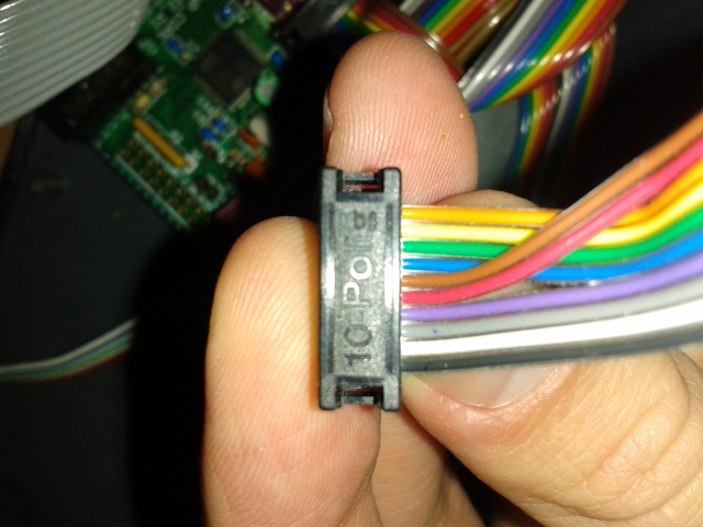
Thereafter use the top row (opposite side to the notch in the header) to connect to AOUT_NG J1. The other side is connected 1:1. These days I would put the black cable on the other way, but it doesn't really matter.
For midiphy LINE_RX, I recommend to use a dedicated +5V supply and leave J3 unjumpered. The ICs use quite a lot of current (100 ohm terminators), which isn't transmitted well down a DB-25 cable.
Any other questions please ask.
-
Peter can correct me if I'm wrong but the workflow is:
Clip: a recorded passage of notes (maybe data)
Track: where clip data is stored. There are six tracks per scene
Scene: a collection of six tracks. Mute states will also be stored, so you can build up layers dynamically.One workflow is to copy clips onto different tracks and flick between scenes to create variation. E.g. if you wanted to drop out all of the tuned instruments and keep the drums going, then build up the parts manually by unmuting them (could also be done within a single clip). Or copy the track and transpose a perfect 5th etc.
I would say it's not meant to be a whole DAW in a box. The idea is to use it as a quick "sketchpad" jamming tool, although Peter has come up with some very inspiring songs using not much more.
-
Thanks for sharing! Has a bit of "Saturate" vibe going on. Did you slave the 909 or sequence from the v4+?
-
Thanks for the photos. From the looks of it, you didn't use that much solder on the LEDs. Did you try reflowing them?
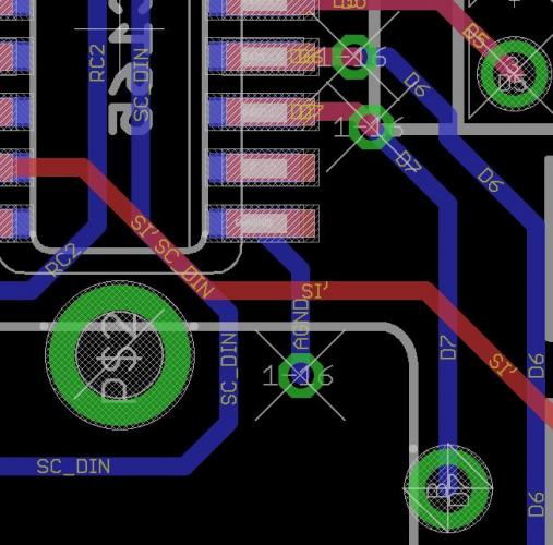
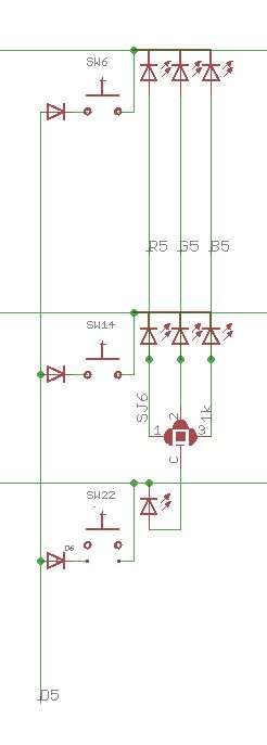
What is the forward voltage of the LED? If it is too high, it could indicate that the soldering temperature was too hot. As everything else works, I don't see how it could be anything else (maybe a broken trace or pad shorted to 0V). Just swap the LED in this case.
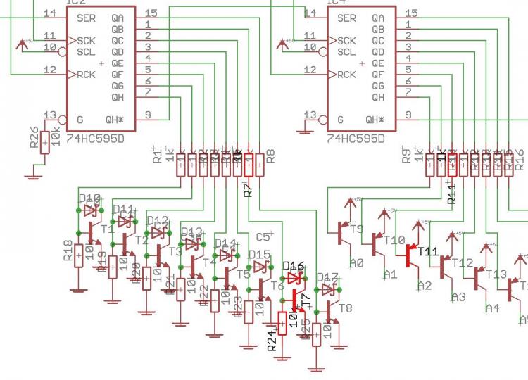
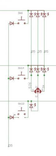
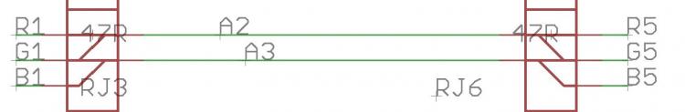
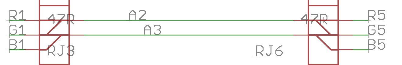
Hence: manually connect the column of the upper red LED to the lower one. If the LED lights, then there is a missing connection between RJ6_1 and the LED. Also test for continuity between the red anode pad and 0V (ground).
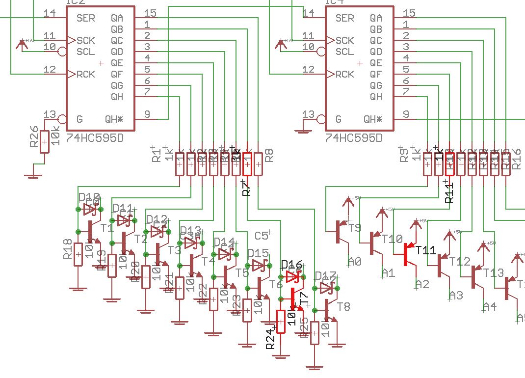
Relevant parts of the schematics attached.
-
A photo would be useful. So the other LEDs of the column light up? MEC and the other superflux? Also nothing else gone in the row?
Is the cathode pin correctly soldered?
Do the DINs work?
When you say you've isolated the LED, you removed it? Did you try one of the spare parts?
You could try to temporarily short to the other red LED in the column or the adjacent cathode in a row.
-
I updated the midiphy BOM tool to reflect the "single quantity" Mouser item. I think this wasn't the case before (as I've ordered single quantities using the same part/link), so my bet is Mouser "updated" that part to require MOQ 25. Did you ask them if you can return them for a refund or credit?
Once again, sorry for the trouble! You could have a whole studio of equipment with your Cores in one corner and the control surfaces in another :).
-
Interesting, as the following part can be ordered in single quantities... perhaps they changed it recently?
The BOM module is updated with this part. Sorry that you're loaded with so many!
-
Digikey has lots of stock, Mouser looks to receive a delivery on 2018-02-04.
If it's super urgent, consider buying the 11-pin version (MDF7-11S-2.54DSA(55)). It might work just to offset the pins one row, but another option is just to cut the edge/last position off if it gets in the way of the mounting hardware.
-
11 goes to the nearer encoder leg. If it's more convenient, just bridge the encoder leg closest to the RN to pin 9 on the resistor network. As long as the bottom trace is still okay, the pull-up just goes the long way around.
-
The good thing about the resistor networks is they aren't hugely sensitive to heat. CMOS chips on the other hand...
I would also recommend a hot air station. I have something similar to what Bruno linked, but the fan is in the main box rather than the "nozzle".
They're useful for other things too, like desoldering (or soldering) large metal parts like heatsinks, pin headers or jacks, or when the PCB designer doesn't use thermal isolation pads on parts attached to the 0V plane.
I even made crème brûlée with it once!

-
 1
1
-
-
This could work too. Though, there may be a risk that you end up ripping of the SMT pads with the force.
You could ask @rbv2 as he had the same issue. A lot of solder/Chip Quik? Maybe even using a lot of solder to immoblise each pin (effectively binding each pin together with solder or even using scotch tape), then clipping?
-
-
Glad that you got it sorted!
Either a hot-air reflow station or TK.'s special trick with a thin wire underneath the SOIC is recommended (this was done for harvesting old chips used in OPL3 modules).
-
Pictures? You can also use the dedicated thread here:
- Did you solder in an isolated resistor network rather than a bussed one? Is the polarity correct?
The random data might indicate floating 165 inputs.
Other ideas:
- Try also with set debug on to see the actual SR positions.
- Is the NG file the LH one, assuming no other boards are connected?
- Is there any conductive flux residue left around the pins?
- Are you using the wCore or something else for testing?
- What is the length of the ribbon cable?
BLM positions are here. SR side is as you would expect, but also attached here for convenience.
Best from snowy Boston,
Andy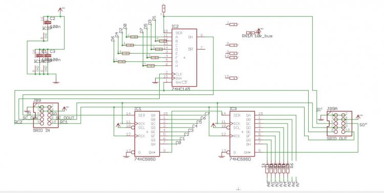
-
I agree with Zam: probably those DAC channels are dead (but do check directly at the pins). The TLV chip is quite sensitive to heat.
-
12 hours ago, Menzman said:
Hi everyone,
just finished my first V4+!
-->Big thanks to Peter and Andy for their great work (and support) to make this machine happen!
After playing around for some hours I found out one issue with my build: Always the eights encoder (8 & 16) do not react as expected. The encoders are jumping in the wrong direction and also opening random-like pages/functions when using them. :-(
Great work and nice pictures!
Are the encoder pins in question shorting out on the pinheaders below? If so, trim the pins a little.
9 hours ago, gbrandt said:Hi Peter,
I'm happy I can contribute a little bit back after lurking all those years :-)
Concerning the LED, i've marked it in red now which means parts where people should be careful in replacing.
And I checked my previously bought MIDI ports again from both Tayda and Mouser and it's true Tayda seems much cheaper and doesn't have a nice metal casing. I marked those, too.
Another thing I noticed, not related to Tayda, is that the MEC switches are out of stock at Mouser now. too many SEQ V4+ builders? :-)
I did find some at RS so might order from there (unless someone has a huge stock and wants to make a nice offer),
but i'll eventually add more columns for other vendorsCheers,
Gerhard
I'd recommend Reichelt for MEC switches. Conrad also sells them, and the caps I think are cheaper there.
-
 On 1/4/2019 at 11:34 PM, latigid on said:
Ah right, these can be very confusing! Also, the way CMOS labels power connections as Vcc Vdd Vss etc. can also lead to mistakes.
I didn't check the pin compatibility (please check!), but this PCB might help:
-
I've done exactly this (with the board outline at the edge) at OSHPark. About half of my boards had missing copper though, as I suppose the router can pull the plating off.
-
Maybe you can get it to a single layer by routing through the SIP header.
For pads to the edge, you could consider a castellated pad/via. Normally the fab will charge extra for it. I'm not sure if it's a good idea mechanically; the simple pin header would be stronger. Or maybe I don't understand your idea.
-
Drum labels sound like an extremely useful improvement!
-
When you look at a male IDC pinheader from the top, the pins are numbered
 ________________________
|02 04 06 08 10 12 14 16 |
|01 03 05 07 09 11 13 15 |
__________----___________
Because we normally connect displays on the rear side, the Core J15 is mirrored, so it's actually
 ________________________
|16 14 12 10 08 06 04 02 |
|15 13 11 09 07 05 03 01 |
__________----___________
Thus the pin numbering starts at 01 in the bottom right corner.
Could you check that these pin numbers correspond to those on the LCD when the cable is connected (with the power off)? Or are the pairs inverted as Bruno says?
Otherwise the pinning on the LCD (unless it's mislabeled) looks to correspond to the Hitachi standard.

Troubleshooting midiphy SEQ v4+
in MIDIbox SEQ
Posted
Very good!
At a guess, R26 is missing, or IC6 is installed without R17/C7. Presumably you haven't tested LED functions yet?
I can provide more help when I see a picture of the board.
Do the encoder pins contact the pin header below? Try trimming the pins, also isolate with a bit of tape.