

latigid on
-
Posts
2,524 -
Joined
-
Last visited
-
Days Won
149
Content Type
Profiles
Forums
Blogs
Gallery
Posts posted by latigid on
-
-
I don't think a custom naming is possible and every synth will likely use different names. But how about editing the respective label file?
https://github.com/midibox/mios32/blob/master/apps/sequencers/midibox_seq_v4/core/seq_cc_labels.c
Then recompile the app with the change implemented.
-
Nice idea! Are they 0402 parts? Were they soldered by hand or preassembled?
-
I think we could use a beta tester :) Peter will be in contact!
-
Very well done and thanks for the beers!?! Hope you can enjoy one yourself -- during the next jam?
Best,
Andy -
-
Great tip! Not sure exactly what temperature you need for heatshrink (maybe around 100°C is fine), but if you use a low airflow rate and just bring the nozzle as close as needs be you should be good.
-
What other CAD software experience do you have? If it's all new and you'd rather not learn, Protocase is still okay. With the possible costs of e.g. a Fusion subscription and a few design iterations of the first attempts you do, probably that $340 is pretty good. If you want to develop your skills and do more case work in the future, definitely go down that route.
Another option would be to design the panel as a PCB, have it fabbed and find a matching case for it e.g. the PT-10. Yet another option is to design an acrylic case that can be laser-cut in 2D and snaps together.
-
For what project do you need an enclosure?
Protocase is awesome and very reasonably priced for one-offs where they take care of everything for you. A great company to work with. The other way would be to machine your own but this requires tools and skills on your part
-
Awesome job!

Almost forgot your serial number #34
-
 1
1
-
-
Yep, the case hardware screws won't work perfectly with the Mouser part. I would personally recommend to use the 4-40 MF standoffs that come with the DB-25 socket as case mounts and keep the black screws for another day. Then you can properly mate a DB-25 cable. If you prefer the look of the >>panhead<< screws, feel free to mangle the thread in the DB-25, but you need nuts on the inside to keep it tight.
-
1
-
-
Building an RH
Building an LH
But Peter shows you the differences here. So if I understand the assembly video you can change the location of the longer cable to suit your case variant.
-
Nice that you got the FLUXTEST working!
Cables should be almost the same lengths for RH/LH, as they have to travel from the left to the right for both cases' cases. :)
-
1
-
-
-
Quote
When there is a Midiconnection from any Loopa MidiOut (DInSocket) --- to a synthesizer --- then it dont boots up >>> now Midiloops because no Input Connected on the Loopa.
Quoteworkaround for now is to connect the Midiouts every time new before booting up the LoopA ---- but i dont want to stress the MidiSockets for ever....
These statements contradict each other. Can you get a state where the LoopA is running and sending MIDI? Or do you mean "boot the LoopA and then afterwards connect the MIDI outs"?
Curious whether you installed the scratch washer and hence grounded the case -- or not? Sometimes these sorts of peculiar things come back to grounding. We can't of course rule out hardware issues (e.g. we know of one dodgy Waveshare Core) or your build process e.g. stressed or overheated pins, shorts etc.
Maybe there is flux residue on the MIDI sockets? Worth another look there.
-
Hard to say if that's a hardware issue or software. IMO best practice would be to make all connections before applying power and avoid hot-swapping...
The LoopA shouldn't care what its outputs are connected to. For your case #4 above, what is connected to your MI1/2? Do you have a MIDI loop? MIDI outs have the 0V connected, so you should consider how the other parts are powered: maybe a so-called "ground loop"?
16 minutes ago, Phatline said:what can that be?:
* the loopa is totally unconnected... then plugin usb cable --- loopa and display boot up - normal
* the loopa is tottaly unconnectet... then plug in midiIN1 or 2 ---then plugin in usb cable --- all ok
* the loopa is totally unconnectet... then plug in MidiIN1 or 2 ---then plugin in MidiOUT1 or 2 or 3 - but without connecting a synth on the other end --- loopa boots up - all ok
* the loopa is totally unconnected... then plugin midi''IN1 or 2 --- then plugin in MidiOUT1 or 2 or 3 - connected to a NordRackII or Dipcore - loopa dont boot up (power led blinks 7 times i think, then it stays on power)
when i then disconnect the Midiout plug after a time it boots up
the last case, isnt pysical stressed --- i connect on one of the midi outs with a loose cable (without a synth on the other end...) --- then it boots up normally.
i tested it with a Nordrack III and DipCoreV2 (cc-looper)
workaround for now is to connect the Midiouts every time new before booting up the LoopA ---- but i dont want to stress the MidiSockets for ever....
-
What did you have in mind? If you want, you could assign it to any function in the HWCFG
SR Pin
1/7* 6*1 for LH, 7 for RH
There is a Moog v-trig converter on there, so a positive gate at the tip of the jack should pull the 165 pin low and enact a DIN event. How about clocking in an analogue tap tempo?
The 3.5mm ring is connected via resistor R4 (USB PCB) to SR pin 5. Probably the 10k value is too high, rather go for 4k7 or less (e.g 1k/2k2). So shorting the ring to 0V will trigger a DIN event there.
And a post from 2011 illuminates the actual intention:
QuoteRômulo aka. Midilab started to implement a footswitch function which is especially useful for live recording and track modifications while playing on a keyboard.
Press&Hold the footswitch to enable record mode, release it to disable record mode. Tap the footswitch shortly to delete the track.
The footswitch can be assigned to a free DIN pin in MBSEQ_HW.V4
So:
#                 SR  Pin
BUTTON_FOOTSWITCH  1   5
or for RH
#                 SR  Pin
BUTTON_FOOTSWITCH  7   5
Please test it if it sounds useful!
Best,
Andy -
Good job!
-
Thanks for the feedback and ideas!
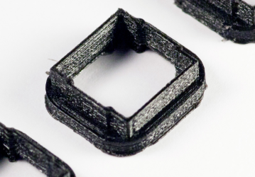
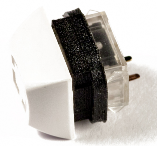
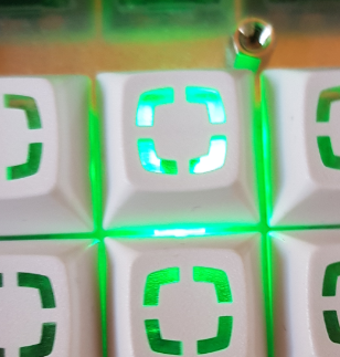
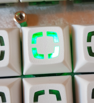
We know there is a bit of LED stray light going on. Some people like it as it reminds them of their backlit mechanical keyboards. But for indicator LEDs it can be suboptimal.
For the smaller 2x3x4/2x5x7 LEDs, a good technique we found was to use a piece of heatshrink tube. It's a great idea to roughen the top too if that is preferred. Sometimes you can also make the LED cloudy e.g. with acetone (nail polish remover) but needs to be tested.
For blocking the light from adjacent Matias switches, we have another solution in the pipeline (more info soon)
-
2
-
-
Never heard of DFU. SWD (or JTAG) is more common.
-
4 hours ago, zaordsword said:
Hi Here,
I would like to know if it is possible to flash the mios Bootloader and mios applications on other cards than STM32F4-DISCO, for exemple on this boards :
https://github.com/mcauser/MCUDEV_DEVEBOX_F407VGT6Try it! Report if it works.
4 hours ago, zaordsword said:I would like to know how it would be difficult to make Mios studio working with newer stm32 board like Teensy 4.0 or Stm32H743 board like https://github.com/mcauser/MCUDEV_DEVEBOX_H7XX_M
Possible but would take much more effort.
-
@keelhauler that's super cute! We do try to make designs cat-friendly :)
-
Awesome!
Thanks for the positive and informative debug reports and have fun with the LoopA :-).
-
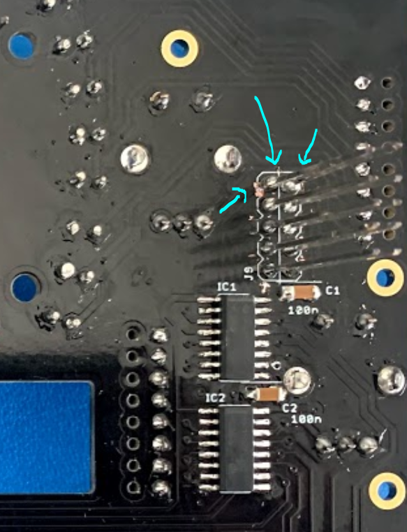
Glad that the OLED issue is solved! Could I ask where/how the broken trace originated?
For the DIN problem, you can recheck the soldering on Core IC1B especially pin 13 (RC2). Make sure that you get contact all the way through the header when the sandwich is assembled. Please reflow the joints to get "volcanoes" rather than "balls".

You will have to be careful not to move the individual pins around because the plastic part that normally holds them together is gone. My approach to soldering the J89 pin header is different to Peter's. I found that you don't have to push the pins all the way to the bottom of the corresponding socket on the Core and there is no need to remove the plastic. The plastic prevents solder flowing through the holes and making blobs that might short out other pins.
----- if you have any spare 2.54mm pin sockets you can use this temporarily on the long end to hold them together.
On the Plate PCB can you provide the part number of the resistor networks? If it is an isolated type the DINs will not work. The orientation is also important.
-
Hmm, did you try reflowing the joints? How is the unit being powered? Is the LoopA firmware loaded? Are you running in test mode (no SD card)?
You could check the above-mentioned pins for shorts to 0V/3v3 or even to each other, so check a) adjacent pins on the J15C header and b) pins on the waveshare breakout,
Happy to take a look at the soldering of the other boards. You can also load MB_NG and check if your DIN is working as expected from MIOS Studio (set debug on).

LoopA V2 Introduction, Features & Support Thread
in MIDIbox User Projects
Posted
Awesome job and thanks for the testing and feedback! Let us know how it goes with the light|shield flex :)