

latigid on
-
Posts
2,516 -
Joined
-
Last visited
-
Days Won
147
Content Type
Profiles
Forums
Blogs
Gallery
Posts posted by latigid on
-
-
Good point about the red. You might be able to block it out with a type of collar or even a gel filter that cuts off ~700 nm.
Anyway, looking forward to more info.
-
Nice work! What sort of layout were you going to do? An isomorphic or square grid? Presumably you'll need a clear housing the bottom (or holes drilled) to get the LED shining through, or do you plan to use other switches (e.g. Gateron)?
-
I asked Fentek, keycaps direct and X-keys if they have ALPS mount and different plastics available.
I've ordered a few Matias and Cherry MX switches to test.
FWIW, the keyboard above can take both Cherry MX and ALPS switches. The backlighting uses a kludge method of bending an LED into the hole normally holding the Cherry MX post. Ideally I'd prefer to have as few PCB holes as possible to make routing easier, so I'll first look at a topside LED under the switch. Other options are "dead bugging" an RGB LED, using "chiclets" holding an easily soldered 5050 mount + pin headers, or even columns of 4.
PLCC would be great if only they had reverse-mount styles, but I can't find any in RGB. In this case it might work to use normal LEDs and attach them with cut resistor legs spanning across the "bottom" and making the solder connections. After the chip was secure, you'd carefully cut the wires apart as not to short the pins.
-
On 11/10/2015 at 10:51 PM, TK. said:
Today I did some experiments with RGB LEDs, e.g. to evaluate Andy's idea to use a single RGB LED as replacement for LED rings around encoders: http://midibox.org/forums/topic/19619-alternative-to-led-encoder-rings-illuminated-red-green-encoders/
Outcome:
- a LED matrix configuration doesn't give us enough brightness levels. E.g. I tried a 4x8 matrix which allows 8 brightness levels for each color, but it turned out that dim values above 4 (50%) don't make a big difference anymore, accordingly the actual resolution was only 2 bit (4 brightness levels)
- therefore I connected the R/G/B LEDs directly to DOUT pins, which gives us up to 16 dim levels and higher brightness (since no multiplexing takes place). Results where much better!
-
In order to generate different hues, I use the HSV color model, and sweep H from 256..0 and V from 0..100% (S always 100%)
See http://colorizer.org for the resulting colors
Script: http://svnmios.midibox.org/filedetails.php?repname=svn.mios32&path=%2Ftrunk%2Fapps%2Fcontrollers%2Fmidibox_ng_v1%2Ftools%2Fgen_colour_maps.pl -
The generated R/G/B Maps are then used in a .NGC file:
http://svnmios.midibox.org/filedetails.php?repname=svn.mios32&path=%2Ftrunk%2Fapps%2Fcontrollers%2Fmidibox_ng_v1%2Fcfg%2Ftests%2Frgb_4.ngc
This example configuration shows, how the RGB hue can be controlled from a single encoder (or via incoming CC event)
Conclusion: if LED rings should be replaced by RGB LEDs, we need 3 dedicated DOUT pins per LED, makes 48 pins for 16 RGB LEDs = 6 DOUT SRs
Line drivers are not required, since the DOUT SRs are strong enough to drive the LEDs.Best Regards, Thorsten.
Seeing how it looks like we're going back to a shift register-driven RGB BLM in 8*4 config, I'm curious if you connected any current source/sink in this setup (if you remember).
-
Round and round and back again...
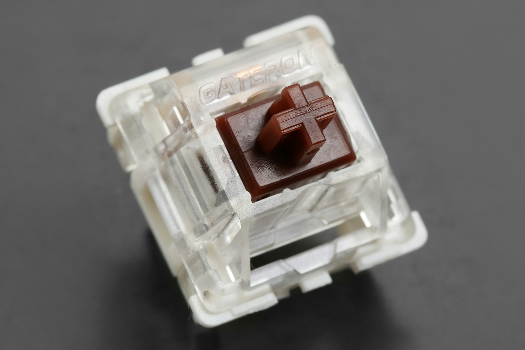
ALPS/Matias seem to do a better job, because you can reverse-mount the LED right in the centre of the switch. Cherry MX have a stabilising pin there.
(clicky one)
https://www.youtube.com/watch?v=qfwJBpeT6TE
A real pity about the fewer cap options though.
-
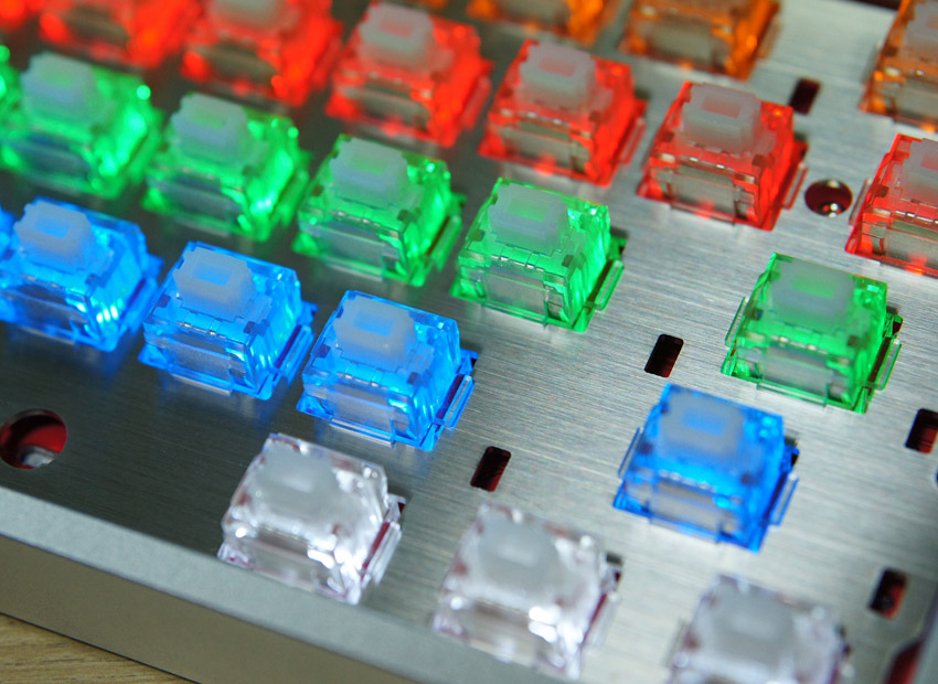
@ilmenator, it's a bit of a toss up, because the bleed likely doesn't come from the bottom (the mounting plate blocks most of the light) but spills over the whole clear switch top. By design the caps sit 3mm above meaning there's a lot of chance for wandering photons. For mech key dudes, I bet part of the appeal is having a coloured "skirt" of light at the base.
The Gateron or Zelio switches have a large cutout lending themselves to other LED options, maybe a narrow angle THT RGB LED raised as high as possible. The downside being it makes hotspots more likely unless there's good diffusion.
Cherry MX normal with LEDs
https://geekhack.org/index.php?topic=54702.0

-
I found the following imgur album a good representation of X-keys clear caps:
Even a tight layout of 18mm works okay:

without caps there's notable hotspots on the clear caps (could be the photo/camera settings):

In the dark:

From this angle you get the idea of the "switch mounting panel"

The black painted keys with translucent "negative" labels look the best IMO.
Apparently RS used to stock these, I can't find them anymore
Back to X-keys, result isn't too bad with mostly black legends:

Looks like quite a bit of colour bleed; fine for bling RGB where you want a rainbow effect, less so for individual indication.
-
 1
1
-
-
Interested in how MIDIboxers use their memory. The main reason for asking is if interior SD cards are okay, or whether it's really needed to have a card on the rear or front panel.
Thanks for participating.
-
It's got that familiar Hawkeye feel, many thanks for sharing :).
-
For AINSER64 you have the choice of a regulated power supply, then the only resistors in circuit are to current limit the LEDs. Notice the filter caps on the ADC Vref .
-
No problem with carbon, especially when they're pull ups/current limiting. Maybe an issue for analogue or where Tc becomes important. But even in AINSER, your pots will be carbon film.
Metal used to be much more $$, now they can even work out cheaper.
-
Of course, migrating from 16F to 18F would be a lot of work, although an interesting challenge :).
I'm actually in three minds about this.
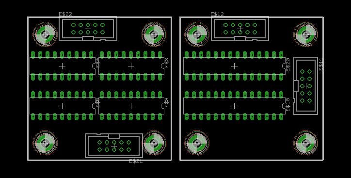
First is to simply redo 4* I2C in a smaller form factor. Easiest but not very creative. Second is to use the PIC18F25K22 with code edits. Swapping 4*DIP18 for 2*DIP28 doesn't make that much difference to PCB area:
Third is to dive in and look at an extended I2C/UART system. Teensy 3.5 springs to mind, as it has 6 UARTs available and 5V compatible IO for $25 in a small package. Could be useful as it seems there's a lot of nice peripherals to be implemented these days.
-
Good plan.
-
You can try swapping U8 (74HC595). U7 would seem to be okay if the matrix responds to buttons. To confirm: this was working at one point?
Also, ensure the CS is connected by J1, closer to the centre of the board, not J2 below it.
-
Yes. If unsure about the orientation of the IDC, (before applying power) test for continuity on the 5V line e.g. the power pins of the shift registers vs. 5V pin on the Discovery Board.
-
On 30/11/2016 at 5:30 PM, u-link said:
Hi there, Signature Plastics answered the following (my request was for something fitting the Matias-mount):
They have a non-recessed fitting mount style available, and
"We can make relegendable keys with
the EX mount. It is unfortunately not possible to make the keys with a clear
top - the relegendable top is clear, but the bottom of the relegendable is
opaque. We can however mold the base out of clear material to make the
entire keycap transparent. Is this something you are interested in? We have
a minimum order value of $100, but I can't give pricing until I know which
route you want to go (opaque base or transparent base).
Thanks!"Hey, thanks for the update. As mentioned, it's looking like the switches will be Cherry MX or equivalent. Also, a recessed mount would be better (have a look at the panel spacing image above), but in any case, there won't be any "front panel" around the keys as there's no room. A good compromise I think would be to use black or dark PCBs for the "switch panel."
Any thoughts on the "X-keys" linked above? They come out at 50c each, though that's without any bulk discounts requested. It'd be good to get proper dimensions of them, but they look to have a lower profile than other caps, also a few mm less in the x/y dimensions.
As far as colour goes, that's a tricky question! How about a milky type of plastic in a neutral colour? The light would then be better diffused than with full transparency. Also, one could paint/spray paint a darker colour over the the translucent cap bottom -- the opposite of what the guy did in the video above. If possible, please get some pricing from them!
Before big decisions are made it would be nice to test out a switch and check the illumination with a given LED.
I've requested samples of the white on black OLED above.
No luck with a vertical socket for SD Cards, although there is one for microSD. Hack approach:
Same principle as using an old floppy cable, but not a great idea as you'd need the panel precise, one of the contacts removed and a plastic guide to align the pins properly. Does the SD have to come out to the panel? It would be easier and cheaper to have a microSD sitting in a normal or hinge type socket. Otherwise you get another PCB breaking out an SMT SD socket to header pins that are soldered or socketed on the main PCB.
The following being the idea of socketed SD:

-
Something else to try is a bypass cap over the supply rails -- noise spikes might cause confusion for Mr. OLED.
Edit: would suggest as close as possible to the pinheader on the display.
-
Maybe try 3V/3V then, this would load the Vreg a bit, but apparently only to 60mA. Could be noise on your USB 5V buss?
-
How did you set the Core LCD voltage jumper?
-
23 hours ago, TK. said:
I remember that I ordered this chip some time ago to work on a Dual-MBHP_IIC_MIDI board, but I'm still unsure if it's worth to work on this. Implementation, documentation and support effort is higher than the benefit (at least at my side)
Actually it would be nice if somebody else could implement an alternative solution, do all the required testing and give long-term support.
Best Regards, Thorsten.
Exactly, it's a question of whether the effort of testing a new layout and code is worth it to save a few bucks in 16F chips and a bit of board space. I can certainly look into it, but I would likely need a bit of help with the firmware.
Well, I checked the assembler -- it's nicely annotated but still a bit beyond me. I.e. I can easily set the baudrate to match the faster CPU but there's lots more going on :). Would you keep the I2C addresses the same but fill separate buffers, or run different ports completely in parallel (presumably the former to maintain compatibility)? If you could suggest a basic direction I can see if it's manageable from my side.
@yogi, I was considering the out-only version to keep things simple. SPI would be an interesting solution (fast enough?), if space/cost wasn't an issue you could interface to another dev board -- even STM32 :).
Best,
Andy -
Okay, I built the app for STM32F1, I didn't try it on my Core.
-
Do you have a PIC or LPC/STM32F4 Core? You should test your DOUT module, but the MIDIO128 app isn't compiled for STM32F1.
Also, you're using an old rev of DOUTX4, so again check your wiring. It's possible to kill CMOS chips, for instance with reversed power connection, so you can swap in a spare.
http://www.ucapps.de/mbhp/mbhp_doutx4_r5.pdf
The correct signal to send to DOUTs is SO, located on the top of the header relative to the polarising notch. Understand too that the connector on Wilba's board is mirrored.
I just tested my F1 Core with DOUT, it works fine but only if you've initialised with
J5_ENABLED 0Copy a new MBSEQ_HW.V4 file to your SD card (comes with the latest firmware) to be sure.
-
Keeping it in the family, the following are 8-bit PICs with >2 UARTs
PIC16F15354
PIC16F15355
PIC18F23K22
PIC18F24J11 okay
PIC18F24J50 okay
PIC18F24K22
PIC18F25J11 EoL(?)
PIC18F25J50 okay
PIC18F25K22 okay
PIC18F25K80 SOIC
PIC18F26J11 okay
PIC18F26J13
PIC18F26J50 low availability(?)
PIC18F26J53
PIC18F26K22 SOIC
PIC18F26K40
PIC18F26K80 SOIC
PIC18F27J13 SOIC
PIC18F27J53 SOIC
PIC18F27K40Basic specs:
		PIC16F88 / PIC18F25K22 / PIC18F24J11 / PIC18F24J50 / PIC18F25J11 / PIC18F26J11 / PIC18F26J50
Data RAM Size:	368 B	1.5 kB	3.72 kB	3.72 kB	3.72 kB	3.72 kB	3.72 kB
Program  Size:	7 kB	32 kB	16 kB	16 kB	32 kB	64 kB	64 kB
CPU Frequency:	20 MHz	64 MHz	48 MHz	48 MHz	48 MHz	48 MHz	48 MHz
Supply Vmax:	5.5 V	5.5 V	3.6 V	3.6 V	3.6 V	3.6 V	3.6 V
Accordingly PIC18F25K22 looks the best as it's 5V and available in good quantities.
Heh. Probably needs a PICkit 3 programmer though...
-
Previously:
I'm wondering about a new design, likely as a separate board(s) wired to 8 DIN5 sockets.
PIC16F88 is still available, and I have the programmer so can flash them. But is this the best way? There are other MCUs with 2/4 UARTs, also dedicated chips for the purpose (fine pitch soldering). Or, is it the simplest way just to dedicate one PIC for every port?
Any thoughts or ideas?

CV / Gate clarification help
in MIDIbox SEQ
Posted
Great! Now you can do the "it's working dance" :). Thanks also for reporting back.
Reflowing joints is always a good idea, and if you have intermittent behaviour often the problem can be solved by checking the ground/0V connection.
Enjoy,