

latigid on
-
Posts
2,524 -
Joined
-
Last visited
-
Days Won
149
Content Type
Profiles
Forums
Blogs
Gallery
Posts posted by latigid on
-
-
http://x0xb0x.cvs.sourceforge.net/*checkout*/x0xb0x/hardware/mainboard.brd?revision=1.1 YMMV
Are you self-etching the PCBs or sending them to a prototyping fabricator?
-

Both AIN_4 and AOUT_4 are working nicely :). The range switches are especially useful for AIN, but I can see the benefit of alternative AOUT ranges with improved accuracy when used as a mod source (rather than a pitch CV). It seems a good idea to use the bipolar option for pitch, otherwise you'll always be transposing. E.g. I think C0 in MIDIbox land is set to 2.00V?
-
You're lucky nILS isn't here, or he'd probably charge a stupid question fee (or make a snide remark)
QuotePrice will be approximately US$200 per complete kit (case with Lexan overlay, PCBs, all parts except SIDs)
-
 1
1
-
-
Here's some more!
***
Hi, the hardware/case is usually the most expensive part, so you should ask yourself what you're willing to spend. Quality normally correlates with price.
You can get a lot of parts from Tayda in Thailand, e.g.
Pots (5-10k are good values)
Switches (take your pick, normally you want momentary ones, perhaps some toggles or rockers. While cheap, these are considered to be quite poor quality, e.g. the moulding resin tends to melt very quickly during soldering.)It's simple to order under the customs threshold for the EU and you'll normally get your parts within 1-3 weeks. Check on their Face* page for a ~monthly discount of 10-15%
http://www.banzaimusic.com/ (Germany)
http://www.watterott.com/de/Komponenten/Mechanisch/Schalter-Taster (Germany)
http://smallbear-electronics.mybigcommerce.com/ (US) -
To clarify the above post: if J2 is used for power, then J17 should be open.
For externally powered Cores, I recommend (and will likely consider) the following style of cable (YMMV, not tested yet):
Heh, just for fun, these are the shipping criteria:
QuoteShipping and handling
Item location: Guangzhou, ChinaShipping to: WorldwideExcludes: APO/FPO, Africa, Central America and Caribbean, South America, American Samoa, Cook Islands, Fiji, French Polynesia, Guam, Kiribati, Marshall Islands, Micronesia, Nauru,
New Caledonia, Niue, Palau, Papua New Guinea, Solomon Islands, Tonga, Tuvalu, Vanuatu, Wallis and Futuna, Western Samoa, Albania, Andorra, Austria, Germany, Guernsey, Ireland,
taly, Jersey, Latvia, Liechtenstein, Luxembourg, Macedonia, Monaco, Montenegro, Svalbard and Jan Mayen, Switzerland, United Kingdom, Vatican City State, Brunei Darussalam, Cambodia,
Hong Kong, Laos, Macau, Bermuda, Greenland, Mexico, Saint Pierre and Miquelon, Iraq, Israel, Kuwait, Lebanon, Afghanistan, Armenia, Azerbaijan Republic, Bangladesh, Bhutan, China,
Georgia, India, Kazakhstan, Kyrgyzstan, Maldives, Mongolia, Nepal, Pakistan, Sri Lanka, Tajikistan, Turkmenistan, Uzbekistan -
There's another jumper that interrupts the power supplied from USB (J17), so for external supply, J17 should be open.
If USB host is unstable, try unbridging the jumpers as described above.
-
-
26 minutes ago, Altitude said:
Hm. Are you talking about the column above the shift button ? Seem to work fine here
Is your shift button pulsing each quarter note when the sequence is running/ illuminated when held down to change modes etc.? I'm using an F1 Core, so it could be related to that.
26 minutes ago, Altitude said:I am working on getting more inputs (namely a keyboard and drum pads) set up and I can seem to figure out how to get them to work correctly. The BLM keyboard mode works fine and the monitor shows activity on the input channels and I have the forwarders turned on for each track. I am sure I am missing something obvious, can anyone shed some light?
Did you configure the routing from the MIDI menu? You have 16 nodes to play with. What do you want to send where?
-
On 31/07/2016 at 7:27 PM, TK. said:
V4.091 is now available under http://www.ucapps.de/mios32_download.html
From the ChangeLog:
MIDIboxSEQ V4.091
~~~~~~~~~~~~~~~~~

   o new parameter type "Chord2" provides an alternative set of 32 chords

   o new parameter type "Aftertouch" allows to send and record channel pressure events

   o CPU load display has been re-adjusted for LPC17 and STM32F4

   o hwcfg/wilba*/MBSEQ_HW.V4: default F1-F4 assignments changed to:
     F1: Track Select, F2: Live Forwarding, F3: Recording, F4: Save All

   o MBSEQ_HW.V4: added new button/LED functions: FX, MOVE, SCROLL

   o MBSEQ_HW.V4: added new LED_MEASURE function which will activate a LED
     when the first step of the measure is played.

   o CC Parameter layer label now prints "#<number>" instead of "CC"

   o Jam page: AStart now starts to record into first step in
     live recording mode (as intended), it starts on the selected step
     in step recording mode

   o Purpose of Record and Live Button & LED change:
     they switch between record (and live) mode w/o changing to the Jam page

   o new button/LED combo: JAM_LIVE and JAM_STEP: they switch to the JAM
     page and select Live resp. Step recording mode

   o BLM16x16+X keyboard can now record into any track

   o Transpose page now allows selection based on Scale

   o New option page item #10 "Initial Gate Trigger Layer"
     (empty or trigger on each 4th step)

   o Event configuration page: new drum track configuration 2*64/2*128

   o AOUT: added suskey function (AKA fingered portamento: slew rate only
     enabled if more than 2 keys are played)
     This function can be enabled in the CV Configuration page

   o removed obsolete (non-working) pattern based scale control

   o fixed LED behaviour in Step View page (corrected display if page is deselected)

   o various minor bugfixes & improvements
Best Regards, Thorsten.
After v4.091 I believe the shift button LEDs on the BLM 16*16+X no longer illuminate. I think this was the case on Saturday, but I can't test today due to my SD card being lost in Munich =). At least with the BLM in test mode the lights work without issue.
-
Sure thing, hence "not impossible."
Everyone can go ahead and design their own DACs, but if there's something similar or even equivalent to one of the existing DACs, integration into MIOS should be easier. E.g. if MAX5500 follows the same code protocol as MAX525 (I need to check), then nothing has to change and it's hopefully no extra work for TK. If the pinout is the same, then I just need to get a chip + adaptor and test it in the current PCB (or Altitude could try with his AOUT boards already prepared for SSOP MAX525).
-
(T)SSOP plus an adaptor is a good idea. I'm not sure if pre-soldered products may be sold in Europe(?). I would prefer to keep the chip coupled as closely as possible to the PCB (+1 on the dual use pads), but it looks like time is up on DIP DACs as you say.
Quad vs. Octal: I'd like to keep the quad layout if possible, although it could be doable to have an octal DAC and two quad control panels. If I can avoid re-routing the DAC board too much I'd be happy :).
Hopefully you can read that.
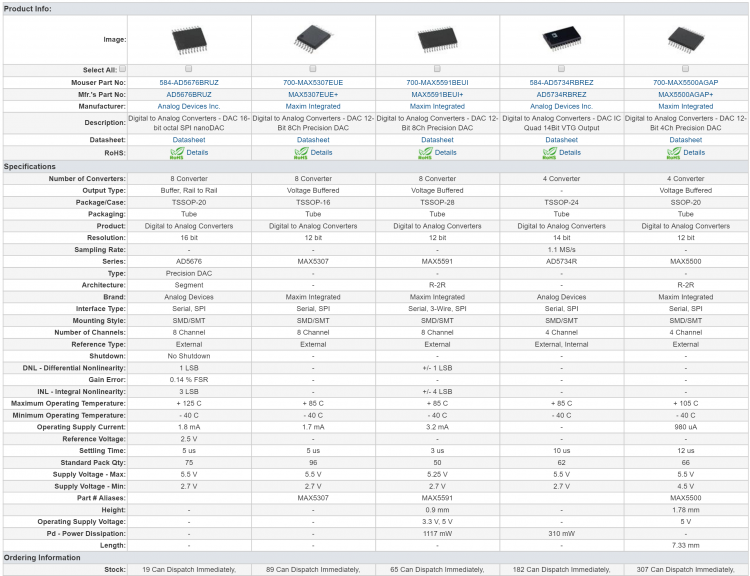
MAX5500A:
- Quad 12-bit
- ±0.25 (worst case ±0.75) LSB integral non-linearity
- ±1 LSB differential non-linearity
- 3.5mV offset error
- 6 ppm/C offset-Error Tempco
- Typical -0.3 LSB gain error
- 1 ppm/C gain-Error Tempco
- Similar pinout to MAX525
-- in fact looks basically like the same die as MAX525
AD5676B:
- Octal 16-bit
- ±1.8 (±3 worst case) LSB integral non-linearity
- ±0.7 LSB differential non-linearity
- ?0.75 (worst case ±2) offset error
- some other parameters are given as percentages
- cost is the same as 2* 5500
- chip layout is a clockwise arrangement: a bit annoying to keep the same order (A B C D || H G F E)
not impossible.
MAX5590B
- 'A' variant is not recommended for new designs... not a good sign
- Octal 12-bit
- ±2 (worst case ±4) LSB integral non-linearity
- ±1 LSB differential non-linearity
- 5/25mV offset error
- 5 ppm/C offset-Error Tempco
- ±20/±40 LSB gain error(? 2/4?)
- 1 ppm/C gain-Error Tempco
- chip layout is a clockwise arrangement: a bit annoying to keep the same order (A B C D || H G F E)
AD5724RBREZ
- Quad 12-bit
- ±1 LSB integral non-linearity
- ±1 LSB differential non-linearity
- ±6mV offset error
- 4 ppm/C offset-Error Tempco
- 4 ppm/C gain-Error Tempco
- actually a better pin arrangement
- expensive
Once the parts arrive I will need to test the MAX525 AOUT to see if the scaling circuit works well in general. Then we could consider an AOUT_3G (?) module.
-
AD5734
-
By no means is it impossible to solder SSOP, but the difference in pitch is significant:
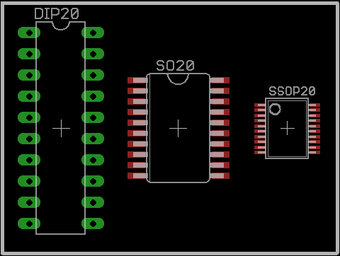
-
MAX5500 (SSOP) could work.
-
I see two problems with the DAC8565: no DOUT for serial chaining, and TSSOP is fairly tedious to solder. Those 4 extra bits aren't too useful considering the error of.. 4 bits!
I'm fine with designing and testing a replacement if one exists!
-
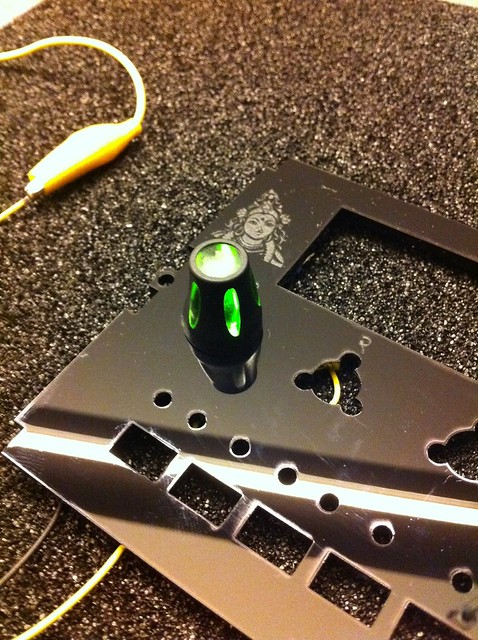
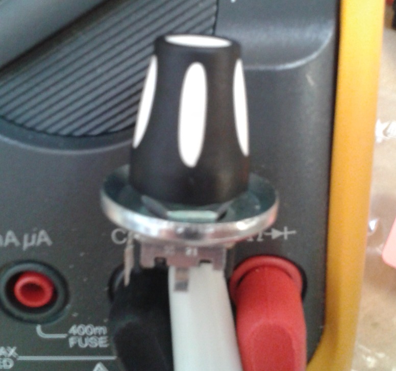
We can do better. This was my idea as a touch sensor for acceleration, but in the end I think the cup washers are a bit big:
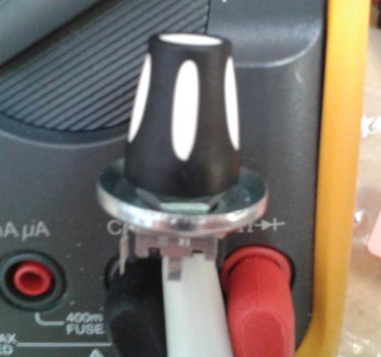
Albs make a clear version of this which looks really nice when illuminated:
-
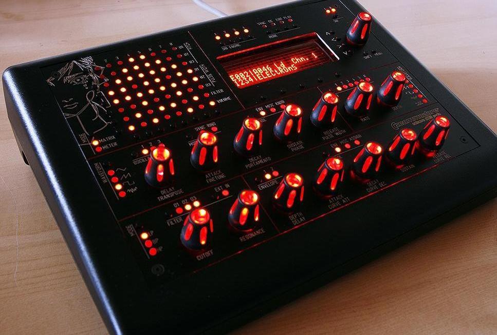
Here's a souped up version (intended for Programma):
- All registers on board.
- 45 degree styles
- Room for OLEDs
- Individual touch sensors, wired to encoder bodies at the moment.
A bit hard to capture the LEDs, but I hope you get the general idea. The touch sensors are set to activate the LEDs and they can be "dimmed" using a MIOS CC value. It's very preliminary for the moment, but eventually the idea is to use the touch sensors to turn on the acceleration function of encoders. That needs a bit of thought though.
-
2
-
Hello, sorry but what's NRPN?
The key to this (potential) issue is whether a USB host connection from the computer is required to boot the STM32F4 on later revisions. For your standalone case, how is the board powered? If it's via a computer, then I guess the USB connection is still present?
-
8 minutes ago, Psykhaze said:
i don't see where the switches should place

Either side of the duo LED (3-pin).
8 minutes ago, Psykhaze said:jacks are those from Thonk ?
or Erthenvar etc. I think Mouser might even stock them. Anyway, they're very widely available.
-
Op amps are pretty good amplifiers :)
TL07x are quite good "Swiss Army knife" chips and you can generally make an amplifier, mixer, inverter, filter etc. with just a few external components. Depending on where the audio is going, you may want a decoupling cap in there to remove DC offset.
...
While I'm here, these are the current PCBs for the "CV toggle."

I decided against the toggle switches, because they're too big and you have to pay ~$5 each for decent quality ones. Tayda have cheaper options but they're generally not well regarded. I've opted for push button DPDTs instead; because a centre-off (ON-OFF-ON) isn't possible, I used two per channel and the second pole is used to illuminate an LED, which effectively tells you what range setting you're in. I was also unhappy with the mounting -- too much space and the 90 degree ribbon connectors were awkward. Now the whole thing is 50mm wide with the processing board stacked below the panel board.
-
1 hour ago, Phatline said:
hi.
what meen "OR" exactly? > do i have to use a other "Sandwitch-PCB" behind the frontpanel when using AIN or AOUT?
The idea is you use:
one Control PCB + one AIN
-- OR --
one Control PCB + one AOUT
(you can't use both in the same "sandwich")The Control is flexible in that in can be configured for either; you stuff different resistors/diodes/solder jumpers, while the SIL headers connect to different parts of the respective PCBs.
1 hour ago, Phatline said:Do i need a Front-PCB @6€ + a AOUT-PCB@6€ to get a 4 AOUT+Trigger-Combi?
Yes. Plus a some sort of DOUT (e.g. SmashTV, MBCV v2).
1 hour ago, Phatline said:What DAC do you plan > a 4Channel? what type?
MAX525. It is expensive but has proven itself as a good DAC. I soldered two AOUT_NG modules, one doesn't work and for the other, channel 1 is non-linear viz. my SEQ tuning. I don't know if that's a problem with the chip; maybe I overheated it whilst soldering?? But checking on Mouser, MAX525 is one of the cheapest DACs available in DIP. There are a few others, but I couldn't find many (any?) with serial out (Tx). It's still listed in active production and if there's sufficient interest maybe I can look at a bulk order. I'd also like to chat with TK. about a possible MUX/DEMUX board. Thus you might have 32 (64?) inputs for ADC and 32 (64) outputs for DAC using SMP08s, and a 74HC595 to generate chip select addresses.
Best,
-
This is a general interest/info post for a new(ish) CV concept.
The green PCBs are 4 channel AOUT and AIN boards. Either one stacks with one blue "Control" board.

AOUT: MAX525 based. I realise that @Altitude also has an AOUT in the pipeline, so I want to explain the pluses for both.
- 8 channel
- more compact (minimum rack real estate)
- DOUT onboard
- lots of clocks and triggers
- US shipping
- more spacious (a bit more ergonomic)
- switchable ranges (0-5, 0-10, +/-5V)
- manual fine tune control
- through hole assembly (no fine pitch SMT)
- new amplifier circuit with precision references and compensated outputs
- EU shipping
- matching panel design with AIN (see below)
Status: I have most of the parts on hand, so this should be tested within a few weeks.
AIN:
- switchable ranges (0-5, 0-10, +/-5V) to optimise ADC levels
- protection against overvoltage (op amp limiting)
- attenuator -- can set to clip the op amp input for interesting CV shapes!
- normalisation of the inputs to +5V -- can use pots as manual CV sources
- 3v3 power from a Core or an onboard Vreg
Status: tested as working from an older proto. Waiting on a few parts to complete it.
Control:
- Eurorack compatible
- Accepts either "Thonkiconn" (PJ301M-12) or PJ301BM jacks
- 4 channel AOUT or AIN
-
4 channel gate/trig/clock with LED
- LEDs are driven from a Schmitt trigger so shouldn't interfere with your power rail
-
1 clock can be set as an input with CV protection and conditioning (even works with a sine wave!)
- this conditioned clock can be sent to a Core e.g. MBCV
-
DPDT (7mm) switches to engage the range functions:
- switch in a resistor to adjust gain settings
-
switch in an offset for bipolar operation
- (you could have +/-2.5V or even +/-10V if desired)
- Duo LED to indicate current CV range
-
configurable adjustment pots
- fine tune with diode deadband for AOUT
- attenuator for AIN
- note: the 9mm Alpha pots fit, but I have some "long shaft" versions on order. They have a knurled shaft and pointer which doesn't require a knob.
- mounting for a DOUT R5 board (see below)
Status: needs to be tested with the AOUT and AIN boards, but the mechanical fits look okay.

^^ just thrown together, I suppose shorter standoffs would be possible.
My design goal for an MBCV example is 2*AOUT and 2*AIN:
- 8 CV out
- 8 gate
- 8 CV in
- 7 clock out
- 1 clock in
You'd have 200mm of PCBs, which is around 40HP of Euro space.
I expect boards could cost 5-6 EUR each.
-
1
-
1 hour ago, k-rAd MB6401 said:
I just played my first solo performance with the seq and a modular and I've never felt more at home. Thank you.
POIDH!
-
25 minutes ago, aramz said:
Hi, I get similar behavior as described by Djordje using my STM32F4discovery as a USB-host Midi Bridge. Trying to play a Yamaha P-80 from a Oxygen61 controller a get plenty of hanging notes. I guess it could be a problem queuing the received midi messages from the USB-host, which are processed in real time and resend to the other MIDI-Ports.
How can this behavior be debugged? Which development environment is need for debugging. Can point someone to related documents, tutorials or application notes?
Best regards, Matthias
Hi Matthias,
What's the version number printed on the Discovery board? Did you try removing the solder bridges as detailed in the post above?
Best,

crimic - electronic setup teaching....
in Songs & Sounds
Posted
Schööne Demo! Accent is mostly quite okay for me ;)
It's great to see how comfortable you are with the setup, and you have a wide range of sounds available.
What's the next plan with the band? GIgs? Recording? Or just more fun jams?