

latigid on
-
Posts
2,516 -
Joined
-
Last visited
-
Days Won
147
Content Type
Profiles
Forums
Blogs
Gallery
Posts posted by latigid on
-
-
3 hours ago, u-link said:
Yes, you are of course right, the case wasn't required, it was just the easiest way to a professional looking device. But at 128 Euro plus 115£ for the front panel from thebeast.co.uk plus however much the back panel cost, the case was by far the biggest cost factor in the build. A cheaper solution would be better. The screen printed metal case with wood sides for the Mutable Instruments Ambika i bought cost 110 Euro altogether incl. shipping. Might even be worth to ask Adrian, the guy that designed it, if he would be up for making one for this project.
I think it was always intended to provide a case for the SEQ -- absolutely one's required if you're playing anywhere other than your attic (hint: @Hawkeye)! It's something that's always puzzled me, as the case is important to every project, but here was almost an afterthought. There've been enough disasters with money going missing that some folks are understandably a bit wary.
I'm in contact with Adrian now and again; he's a nice guy with lots of skills and contacts. Another option is Protocase, like I did with the BLM16*16+X. That one was complicated though as it required studs, milling, threading and precision bending. Great quality and accuracy though.
3 hours ago, lis0r said:Sure, more options are great. It'd be nice if it wasn't made incompatible, though, especially if it doesn't result in a significant cost difference. It'd be nice if the boards enabled users to express their design preferences, rather than mandated a cheap end result.
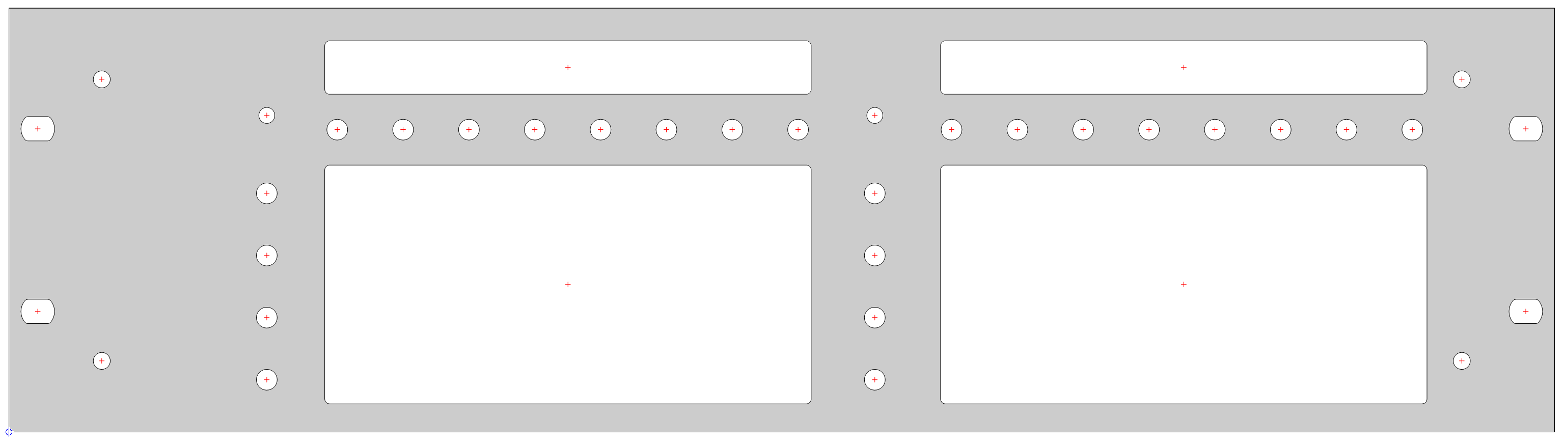
I get what you're saying about reusing the existing parts. I will try to maintain the sizes, but we've gone and squashed a whole extra row of buttons in, and they're quite a bit larger than the TL series. In the end, this is a new project and if things have to change, they will. Just thinking about the idea of metal reinforcement, the panel will be mostly holes and cutouts, so it won't be very strong.

(~$70 for one-off).
I'm not discouraging anybody, so please keep up the opinions. Better still are solutions to things like mechanical strengthening, mounting options, part suggestions etc.
If people want a cheap SEQ, they should stick with the Wilba version. The switches and keycaps alone will likely cost more than the "parts kit" for the former. But I've tested the Matias switches and they light up quite nicely. I'll to look at methods of reverse-mounting LEDs of decent brightness.
-
2 minutes ago, lis0r said:
The images I saw seemed to have space at the left and right edges? Could the bolts not go there, perhaps with reinforcing struts behind to prevent flexing?
Maybe something like that, yes :). Some sort of interior panel or mounting rails would also give valuable room to mount things like the Core/AOUT/line driver etc.
-
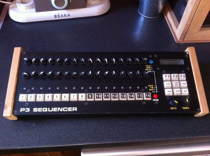
If you read back, there is no front panel between the keycaps. This is fixed by the 19mm spacing for switches and keeping a 3U height. It's quite commonly done on mech keyboards and the P3 shown above. But it means the boards can't hang off the front panel, at least not where the switches are. It could be done another way, e.g. angled rails or chunky acrylic. But at some point you need to make up that angle as screws can't go around corners.
Maybe it makes sense to go for 4U for extra breathing space.
-
A sloping case would need something like these:
https://www.ettinger.de/en/product/05.23.401

As it is, the internal arrangements will make even 3U quite difficult. It'll be very hard to make a thin case, mostly due to the F4 Core dimensions.
-
Try http://thebeast.co.uk Not sure if he stocks the case, but will likely do the front and rear panels.
Heidenreich in Germany do the cases you see. There was a small order done earlier in the year.
FWIW it's not an "alloy" case, but maybe "alu" or "anodised"
-
I suppose +5V.
-
It's still hard to tell from your photos, but it's possible the unlabelled pins on the Base PCB female header are in fact connected to pins 15 and 16. This isn't shown on the current board layout on the wiki, so check with your meter/your eyes to see any PCB traces.
In this case, the header assembly should work with no fly wiring.
And I bet that's the case otherwise we'd have more troubleshooting threads :).
-
-
Alright,
Presuming you have something like this:
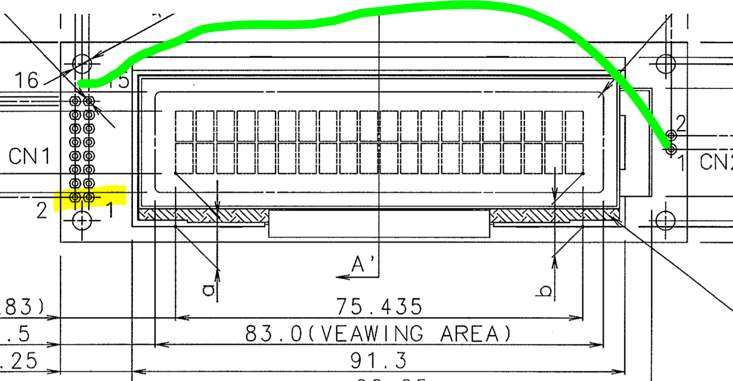
http://www.kyocera-display.com/SiteImages/PartList/SPEC/C-51505NFQJ-LW-ALN_Eng.pdf
Notice the backlight pins are on the opposite side to "normal" LCDs.
Check the base PCB layout. You need to reroute the backlight pins to the base header.
-
 1
1
-
-
Wait a sec...
The LCD header has 2*8 pins, but they don't line up with the PCB header?
Better pictures needed!
Don't turn on the power until everything is correctly aligned.
-
1
-
-
Ah okay, looks too thick for an OLED anyhow. You need to connect the backlight on the right side of the board, i.e. the opposite edge from the header pins. Check the polarity!
-
Are you using an OLED display? These don't use the backlight pins.
-
No real quote as of yet from SP.
As far as the case goes, I'm doing my best to constrain everything to the same dimensions as Wilba. But it will likely need to be mounted straight on though, as the boards rely on being fixed to the bottom via standoffs. For a sloping case it'd need angled brackets or thick acrylic.
I'm aiming for something thin and flat, maybe a two-piece 3mm alu case where the front is bent around to create a side. Wooden end cheeks for sloping desktop use?
With keycaps, the main driver will be cost (as we are a bunch of cheap-asses :P ). I asked if SP would paint translucent caps, even 4 sides with one layer removed by us. They said it would be expensive, but available as an option. Maybe a spray can and remove one layer like the video above?
Something like this:

is perfect (if only relegendable) but sadly not doable by them.
AFAIK laser etching is commonly done, but would add to the expense. I'm still keen for a set of blanks with labels printed at home as needed.
My switches came, I think I prefer the heavier action e.g. Cherry black over red. The Matias switches are fine but are completely flush on the bottom. They'll need some sort of shine through as @ilmenator suggested.
-
As tago is after something specialised, namely combining DIN, DOUT and DIOMATRIX (apart from a nicer pinout, I still don't understand why a DIOMATRIX is required) on one PCB, the onus is on him to get the boards fabbed himself (as already mentioned). There are value-added considerations that go beyond a cheap price from China:
- learning how to use the software properly
- learning the process of ordering, although it's not too difficult
- spending many hours/days/weeks on each design
- making fatal errors on the PCB meaning you have to pay for another run
-
quality considerations, though the standard has increased significantly in recent years
- arguably you're in a better position by dealing with the company directly if such issues arise
- also it's less important for small quantities only bought for yourself
- perhaps buying software, though there are libre programs like KiCAD
The upsides are saving some money and you might say learning a new skill (the essence of DIY).
The decision to open source the gerber or board files for MBHP would be at the discretion of TK. and/or SmashTV. For the latter, this would undermine his prospects as the de facto provider. If you value his service, especially for other PCBs like the Core etc., consider the situation where he can't continue due to lack of demand across the whole shop.
@phat: DOUTX4 is the default way of outputting clocks gates and triggers, so quite relevant for SEQ and MBCV users.
-
2 minutes ago, tago said:
You're totally right, but i have too many tasks in front of me. Some things have to be done with a simple solution.
Good point, why do the work yourself when others can do it for you, right? It's much easier than learning
-
- the latest DIN/DOUT layouts are not available
- I have a board 100*100mm with 6 DINX4 and 4 DOUTX4 on it, some SMT, PM if you want one.
- why do you want DIOMATRIX as well as DIN as well as DOUT? -
You should reflash the bootloader by using the ST LINK side of the Discovery Board, then proceed with the application update.
-
You make changes in the MBSEQ_HW.V4 file located on the SD card. You can remove the card and edit on the computer or use the file browser in MIOS Studio.
-
Pimp My Keyboard is the "retailer" for Signature Plastics -- what I think happens is they supply bulk runs and put the excess on the shopfront.
The little window is mainly designed for Cherry MX, which have the LED in this location. As said already, this limits the switch illumination to the "north" part (or the "south" if you rotate 180 as some keyboards do). I have a few of the Matias switches (and a "sampler" for Cherry MX) arriving today. The drawings don't show it, but if the switches have enough room on the bottom, I'd like to put a low-profile SMT LED right in the centre. The plunger/slider of the switch is opaque, which should mean the light is diffused around the internals of the switch.
-
Nice! Do you have acrylic windows installed/planned?
-
Just discussing with keycaps direct now. I'm leaning towards the DCS-type of switch as it sits just over 1mm lower and allows the front part to be labelled more cleanly. The angles are a bit shallower.

Let's borrow some Sequentix images ;)

here the switches are squeezed into the minimum spacing, and use quite high caps. There's no panel between switches (same as proposed for my layout).
Alternative panel with DSA relegendables?
Cirklon looks like it uses DSA (notice the "spherical tops") with bigger spacing

this also gives an idea of relative heights; the encoders are sunken into the panel as the switches sit very high up.
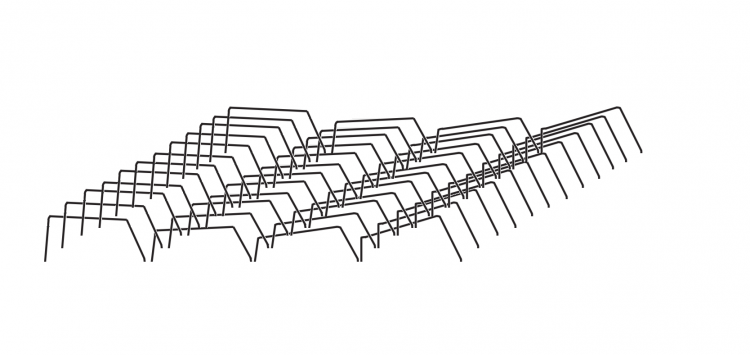
A grid of DSA looks like this:

Whereas DCS are much smaller at the top:

I imagine the cheapest way to go would be to order only one type of cap, so here's the side profiles:
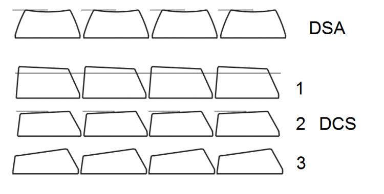
or, the variably angled profile as intended:
maybe more ergonomic? Or weird?
-
Technically the MIDI outs are running on UARTs, so it should work within standard MIDI spec. The I2C module should be fairly close to the Core.
Maybe the problem can be simplified on the other end: one or two DIN MIDI with a thru box on the other end. This depends on how much data you're sending and how important clocks latency etc. are.
MIDI thrus seem to be done with some sort of CMOS buffer (inverter/NAND etc.). Or you could consider the KissBox and send over ETH.
-
If it's only MIDI outs that you need, you gain 4 just by wiring to the correct pins on the F4 disco board/J11E (+resistor), and adding a pull up to +5V for the MIDI- signal.
Unless your diagram is incomplete and you're already maxed out on MIDI IO and Quad IIC...
-
Hi Jay,
I don't have much experience with MIDIO or PIC8 stuff, but I think your "device_id_xx" hex files are simple ways to reset the Device ID to xx without reflashing via a PIC burner.
Before uploading hex, make sure the MIDI communication works using "Query." It's only possible to communicate with PICs holding the same Device ID as selected at the left of screen.
Pressing Query should tell you the application installed on that PIC. If it isn't MIDIO v2, you need to upload a new version:
http://www.ucapps.de/mios/midio128_v2_2c.zip found on the "MIOS8 download" section of ucapps.deThe following gives you info on MIDIO:
http://www.ucapps.de/midio128_v2.htmlA useful config tool is integrated into the Tools menu of MIOS.


MIDIbox SEQ new frontpanel idea
in MIDIbox SEQ
Posted · Edited by latigid on
Thanks, it's not 100% accurate but gives a general idea. Now imagine if the north and south edges were bent 90 degrees and formed a U-shape. This adds significant strength to the metal and could allow for panel mounting.
The switches are indeed already plate-mounted (using the same PCB that holds the encoders and aux switches). Still, the plate/PCB needs something to fix to! My experience with the BLM is that you need mounting points at least every 75mm or so. The smaller PCB in the current work will help, but it needs consideration.
I think I'd be okay with soldering an STM32F4, but you lose the valuable ST-LINK part, so need an FTDI programmer or similar. These would put the project out of reach for many people. Let's see how the jigsaw puzzle pans out.
Heh, I think you can use the Discovery Board as a programmer :)
More edits: Discovery has an okay power regulator and an ESD snubber for USB OTG, and the whole thing is very affordable. If at all possible I'll try to keep using it.