

latigid on
-
Posts
2,516 -
Joined
-
Last visited
-
Days Won
147
Content Type
Profiles
Forums
Blogs
Gallery
Posts posted by latigid on
-
-
Strange LCD issue. Anything to do with the voltage selector?
On another note:
If anyone has working/semi-working MBCV v2s, perhaps you'd like to contribute to the discussion of my prototype control surface here? We need more input on the best way to implement voice and menu structures. Thanks! -
I have a concept and PCBs for scaling CVs
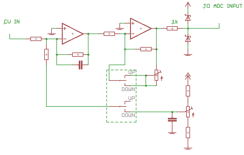
The circuit isn't exactly the same as it uses a rail to rail op amp instead of clamping diodes and the offset is a precision +5V source. I have it built up but I think it needs troubleshooting. Maybe I can have a go today.
For your other points: I don;t think the zeroscope is not quite released yet, and I suppose it will be in the form of PCBs.
Trouble with I2C chips is that these data lines are normally reserved for MIDI outputs, but it could work for a custom application. In other words, it would be great to have common modular blocks that are usable across several applications (like MBCV).
For mounting OLEDs, you might be interested in this:
-
This is for MBCV v2, which I'm working on with TK. (when he has time).
What's happening is the digital waveforms are visualised on the scopes in parallel with the analogue output.
Audio inputs will need amplification, but modular levels need attenuation/limiting and offsetting. You can't feed over- or negative voltages into the Core IO pin. (3.0V nominal peak voltage btw.)
This type of ADC is probably only useful for slow-ish waveforms. The accuracy (jitter) is reportedly better for AINSER, but at a cost of slower transfer rates as the digitised signal runs over SPI if I recall properly. I'm wondering if a proper ADC is a better solution, we can maybe look at some of Olivier's (Mutable Instruments) designs.
So at the moment, ADC for the Core is a concept rather than a proven solution.
Similar things are being developed elsewhere though
https://www.muffwiggler.com/forum/viewtopic.php?t=157649
-
Very nice! Next time with a headmounted GoPro!
What's that you're tweaking just underneath the mixer?
Best,
-
You can even use the second MIDIbox as an interface for the first, you'll just have to configure a MIDI router in software.
Otherwise you might have to get your screwdriver out and enforce the bootloader with the blue button.
-
Could you try to upload this one (F4 variant) and the SEQ app thereafter?
http://www.ucapps.de/mios32/mios32_bootloader_v1_018.zip
-
BTW, was the SEQ functioning properly when you bought it?
-
What operating system are you using? The standard MIDI drivers of Win10 didn't work for me but some kludging with the GM5 MIDI driver seemed to help.
What MIDI interface are you using? It might be on the blacklist (check MIDIbox dokuwiki). DIN MIDI goes much slower compared to the USB version.
It could be that the bootloader is corrupted?? Do you get a valid MIDI over USB connection when holding down the blue button at power on/reset?
Both the Newbie and Expert info pages are useful:
http://www.ucapps.de/mios32_bootstrap_newbies.html
http://www.ucapps.de/mios32_bootstrap_experts.htmlI'd suggest checking to see if the bootloader can be accessed, if not it can be re-flashed with ST-link.
You might play around with updated MIDI drivers:
http://www.ucapps.de/gm5/midibox.org_gm5_X64_1.0.10.zip(assuming a 64-bit OS).
-
This is a SEQ V3 owing to the PIC Core and banksticks. I would suggest that you start from the cost price of the parts and go down from there. It's also a good idea to list your location for currency/shipping estimates.
Or, grab a new Core module and an AOUT and go nuts with your Eurorack. The SEQ kicks serious ass in modular land.
-
If you look at the schematic, the LEDs are arranged in a 16*16 matrix.
- Anode columns are driven by DOUT pulses on SR3+4, while cathode rows are sunk by SR1+2.
- All cathodes of each LED ring are connected to one DOUT pin (it's serving as a path to ground).
- Similarly, all anodes of ring(n) LED(x) are connected, so every ring(n) LED1 is connected, every ring(n) LED2 etc.
If there are any shorts to ground (e.g. if you scratch and bridge to the soldermask while installing an LED) then you can get unintended lighting.
-
Did you revert the sink mask (the driver chips invert the switching polarity)?
-
It's not too clear, but it seems you now have a problem with the matrix not being properly connected and the rows are trying to sink through other channels.
Are there any soldering issues around the 220R networks or the driver ICs? You could also try swapping the drivers to see if it's located on those chips.
-
Are you using the Darlington drivers? Are the shorted pads connected to ground or any power rail?
The schematic might also help: http://jeromebo.free.fr/Wiki/Schematic.pdf
For me, it's quite unusual that only one LED of a matrix is failing; usually it's a whole row or column. As a last resort you could cut the traces and wire manually, considering that this may break more connections in the matrix.
-
Did you try replacing the LED?
-
Perhaps try to swap around the shift registers to see if the problem follows. There shouldn't be a short between the LED pins except when the matrix is being driven. Also check the associated resistors.
-
Just the buttons and encoders? Sure thing. But the illuminated encoders and displays need the big brother. I know there's Arduino code for WS2812s, it just depends on what you want to do with it. Who knows, maybe there'll be a new F7 Core design that could be made much smaller.
-
Yes and yes.

Or even 3 for 48 encoders -- the board width will likely be 150mm, so right at the limit for a 19" rack, but the best "case" scenario will be a clear or smoky acrylic to let the OLEDs shine though.
-
I'm currently working on a layout using 4*4 illuminated encoders, see some of my other threads. If possible I will integrate the shift registers and displays on the same board (half the PCB cost). I'm just trialling an idea for encoder acceleration at the moment.
-
 1
1
-
-
7 hours ago, Psykhaze said:
Is there any schematic on how to connect WS2812 LED (matrix?) to DOUT?
Serial chain from J4B, pin 6 (SC) I think.
-
Something else to keep an eye out for:
-
Confirmed on my end, I additionally tried to change the port settings to MIDI IN 3 (F1 Core, no note limits) without success. Hopefully it's a simple enough software fix.
-
If this only includes the silicone and FSR sheets that's still very expensive. If you don't need velocity sensing you could think about using adafruit (e.g. BLM) or Sparkfun (can be WS2812 enabled) pads which are much cheaper.
Something I don't think you've considered yet is the sensor design. You need interleaved PCB traces (ENIG plating is best) to detect different resistances as velocity changes. Unless you can clone the AKAI PCB exactly you'll need lots of trial and error to get it right. Core STM32F4 has 8 ADCs but they're apparently not that good. There's a board called AINSER which runs over SPI (I think) and might do a better job, but transfers are slower.
If money and time are no problem, go for it of course. But if you want something that works for cheap I'd consider an existing solution e.g. Novation Launchpad Pro (8*8, illuminated, velocity/pressure sensitive) for <$300.
-
Good for DIY, but for the price I would buy a pre-built unit (e.g. MPD218 = $100) and just send the MIDI out.
-
Jumping in headfirst!
I think I confused KiCAD with Diptrace, the latter has limits on size/number of pins unless you pay.
All PCB software has very steep learning curves. My advice is to start with simple boards first, and if that works out go for larger ones. It's very likely that you will make an error (I know this from experience!) and it could waste some money if these are big PCBs.
Some very basic things about design:
- Scanning in vector objects to use as layers is not recommended. Boards are a complex stack up of copper, mask and silkscreen layers, and holes/milling.
- When you connect a net in the schematic editor, this creates an "airwire" for you to join in the board editor. This guides you on how to layout the PCB.
- PCB fabricators accept gerber files, which are the different layers in an vector format, standardised. Few take layout files. I know the gerber generation in EAGLE is pretty good.
Start small, dream big!
-
1
crimic - DiscoDonna
in Songs & Sounds
Posted
Always nice to see the BLM in action :)